|
数据搜索系统,热门电子元器件搜索 |
|
|
数据搜索系统,热门电子元器件搜索 |
|
AD8228ARMZ-R71 数据表(PDF) 20 Page - Analog Devices |
|
|
|||||||||||||||||||||||||||||
AD8228ARMZ-R71 数据表(HTML) 20 Page - Analog Devices |
|
|
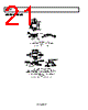
20 / 25 page  AD8228 Rev. 0 | Page 19 of 24 APPLICATIONS INFORMATION DIFFERENTIAL DRIVE Figure 48 shows how to configure the AD8228 for differential output. The advantage of this circuit is that the dc differential accuracy depends on the AD8228 and not on the op amp or the resistors. This circuit takes advantage of the precise control the AD8228 has of its output voltage relative to the reference voltage. The ideal equation for the differential output is as follows: VDIFF_OUT = VOUT+ − VOUT− = Gain × (VIN+ − VIN−) Op amp dc performance and resistor matching determine the dc common-mode output accuracy. However, because common- mode errors are likely to be rejected by the next device in the signal chain, these errors typically have little effect on overall system accuracy. The ideal equation for the common-mode output is as follows: VCM_OUT = 2 − + + OUT OUT V V = VREF For best ac performance, an op amp with at least 3 MHz gain bandwidth product and 2 V/μs slew rate is recommended. +IN –IN REF AD8228 VREF 10kΩ + – AD8641 +OUT –OUT 10kΩ Figure 48. Differential Output Using an Op Amp PRECISION STRAIN GAGE The low offset and high CMRR over frequency of the AD8228 make it an excellent candidate for bridge measurements. As shown in Figure 49, the bridge can be connected directly to the inputs of the amplifier. 5V 2.5V 10µF 0.1µF AD8228 +IN –IN 350Ω 350Ω 350Ω 350Ω + – Figure 49. Precision Strain Gage DRIVING A DIFFERENTIAL ADC Figure 50 shows how the AD8228 can be used to drive a differential ADC. The AD8228 is configured with an op amp and two resistors for differential drive. The 510 Ω resistors and 2200 pF capacitors isolate the instrumentation amplifier from the switching transients produced by the switched capacitor front end of a typical SAR converter. These components between the ADC and the amplifier also create a filter at 142 kHz, which provides antialiasing and noise filtering. The advantage of this configuration is that it uses less power than a dedicated ADC driver: the AD8641 typically consumes 200 μA, and the current through the two 10 kΩ resistors is 250 μA at full output voltage. With the AD7688, this configuration gives excellent dc perform- ance and a THD of 71 dB (10 kHz input). For applications that need better distortion performance, a dedicated ADC driver, such as the ADA4941-1 or ADA4922-1, is recommended. IN+ VDD REF GND AD7688 IN– 0.1µF +5V ADR435 GND VIN VOUT 0.1µF +8V 0.1µF 10µF X5R 10kΩ 10kΩ 0.1µF 510Ω 0.1µF 510Ω 0.1µF 0.1µF AD8228 +IN –IN REF +8V –8V 0.1µF 0.1µF –8V +8V AD8641 10kΩ 10kΩ Figure 50. Driving a Differential ADC |
|
|
链接网址 |
| ALLDATASHEET是否为您带来帮助? [ DONATE ] |
关于 Alldatasheet | 广告服务 | 联系我们 | 隐私政策 | 数据表链接 | 链接交换 | 制造商名单 All Rights Reserved©Alldatasheet.com |
| Russian : Alldatasheetru.com | Korean : Alldatasheet.co.kr | Spanish : Alldatasheet.es | French : Alldatasheet.fr | Italian : Alldatasheetit.com Portuguese : Alldatasheetpt.com | Polish : Alldatasheet.pl | Vietnamese : Alldatasheet.vn Indian : Alldatasheet.in | Mexican : Alldatasheet.com.mx | British : Alldatasheet.co.uk | New Zealand : Alldatasheet.co.nz |
|
Family Site : ic2ic.com |
icmetro.com |
 Chinese ▼
 English
 Chinese
 German
 Japanese
 Russian
 Korean
 Spanish
 French
 Italian
 Portuguese
 Polish
 Vietnamese
 Indian
 Mexican
 British
 New Zealand