|
数据搜索系统,热门电子元器件搜索 |
|
|
数据搜索系统,热门电子元器件搜索 |
|
AD8003ACPZ-R2 数据表(PDF) 13 Page - Analog Devices |
|
|
|||||||||||||||||||||||||||||
AD8003ACPZ-R2 数据表(HTML) 13 Page - Analog Devices |
|
|
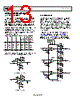
13 / 17 page  AD8003 Data Sheet Rev. C | Page 12 of 16 APPLICATIONS INFORMATION GAIN CONFIGURATIONS Unlike conventional voltage feedback amplifiers, the feedback resistor has a direct impact on the closed-loop bandwidth and stability of the current feedback op amp circuit. Reducing the resistance below the recommended value can make the amplifier response peak and can even become unstable. Increasing the size of the feedback resistor reduces the closed-loop bandwidth. Table 5 provides a convenient reference for quickly determining the feedback and gain set resistor values, and the small and large signal bandwidths for common gain configurations. The feedback resistors in Table 5 have been optimized for 0.1 dB flatness frequency response. Table 5. Recommended Values and Frequency Response1 Gain RF (Ω) RG (Ω) RS (Ω) −3 dB SS BW (MHz) Large Signal −3 dB BW Large Signal 0.1 dB BW −1 300 300 0 734 668 -- +1 432 N/A 24.9 1650 822 -- +2 464 464 0 761 730 190 +5 300 75 0 567 558 165 +10 300 33.2 0 446 422 170 1 Conditions: VS = ±5 V, TA = 25°C, RL = 150 Ω. Figure 38 and Figure 39 show the typical noninverting and inverting configurations and recommended bypass capacitor values. FB AD8003 10µF 0.1µF RG RS +VS VO VIN RL – + VO +V –VS –V 10µF 0.1µF RF Figure 38. Noninverting Gain FB AD8003 10µF 0.1µF RG +VS VO VIN RL – + VO +V –VS –V 10µF 0.1µF RF Figure 39. Inverting Gain RGB VIDEO DRIVER Figure 40 shows a typical RGB driver application using bipolar supplies. The gain of the amplifier is set at +2, where RF = RG = 464 Ω. The amplifier inputs are terminated with shunt 75 Ω resistors, and the outputs have series 75 Ω resistors for proper video matching. In Figure 40, the POWER DOWN pins are not shown connected to any signal source for simplicity. If the power- down function is not used, it is recommended that the POWER DOWN pins be tied to the positive supply and not be left floating (not connected). In applications that require a fixed gain of +2, as previously mentioned, the designer may consider the ADA4862-3. The ADA4862-3 is another high performance triple current feedback amplifier. The ADA4862-3 has integrated feedback and gain set resistors that reduce board area and simplify designs. +VS 10µF 0.1µF –VS 10µF 0.1µF +VS 10µF 0.1µF –VS 10µF 0.1µF 75 Ω 75 Ω GIN 21 22 19 24 RF 464 Ω 75 Ω RG 464 Ω 75 Ω RIN PD1 3 2 4 PD2 PD3 1 +VS 10µF 0.1µF 75 Ω 75 Ω BIN GOUT ROUT BOUT 16 17 15 18 13 5 23 14 –VS 10µF 0.1µF 6 RF 464 Ω RG 464 Ω 20 RF 464 Ω RG 464 Ω AD8003 Figure 40. RGB Video Driver |
|
|
链接网址 |
| ALLDATASHEET是否为您带来帮助? [ DONATE ] |
关于 Alldatasheet | 广告服务 | 联系我们 | 隐私政策 | 数据表链接 | 链接交换 | 制造商名单 All Rights Reserved©Alldatasheet.com |
| Russian : Alldatasheetru.com | Korean : Alldatasheet.co.kr | Spanish : Alldatasheet.es | French : Alldatasheet.fr | Italian : Alldatasheetit.com Portuguese : Alldatasheetpt.com | Polish : Alldatasheet.pl | Vietnamese : Alldatasheet.vn Indian : Alldatasheet.in | Mexican : Alldatasheet.com.mx | British : Alldatasheet.co.uk | New Zealand : Alldatasheet.co.nz |
|
Family Site : ic2ic.com |
icmetro.com |
 Chinese ▼
 English
 Chinese
 German
 Japanese
 Russian
 Korean
 Spanish
 French
 Italian
 Portuguese
 Polish
 Vietnamese
 Indian
 Mexican
 British
 New Zealand