|
数据搜索系统,热门电子元器件搜索 |
|
|
数据搜索系统,热门电子元器件搜索 |
|
LMV331M7 数据表(PDF) 10 Page - National Semiconductor (TI) |
|
|
|
|||||||||||||||||||||||||||||
LMV331M7 数据表(HTML) 10 Page - National Semiconductor (TI) |
|
|
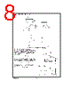
10 / 21 page  Application Circuits (Continued) Pulse generator with variable duty cycle: The pulse generator with variable duty cycle is just a minor modification of the basic square wave generator. Providing a separate charge and discharge path for capacitor C 1 gener- ates a variable duty cycle. One path, through R 2 and D2 will charge the capacitor and set the pulse width (t 1). The other path, R 1 and D1 will discharge the capacitor and set the time between pulses (t 2). By varying resistor R 1, the time between pulses of the gen- erator can be changed without changing the pulse width. Similarly, by varying R 2, the pulse width will be altered with- out affecting the time between pulses. Both controls will change the frequency of the generator. The pulse width and time between pulses can be found from: Solving these equations for t 1 and t2 t 1 =R4C1ln2 t 2 =R5C1ln2 These terms will have a slight error due to the fact that V max is not exactly equal to 2/3 V CC but is actually reduced by the diode drop to: Positive Peak Detector: Positive peak detector is basically the comparator operated as a unit gain follower with a large holding capacitor from the output to ground. Additional transistor is added to the output to provide a low impedance current source. When the output of the comparator goes high, current is passed through the transistor to charge up the capacitor. The only discharge path will be the 1M ohm resistor shunting C1 and any load that is connected to the output. The decay time can be al- tered simply by changing the 1M ohm resistor. The output should be used through a high impedance follower to a avoid loading the output of the peak detector. Negative Peak Detector: For the negative detector, the output transistor of the com- parator acts as a low impedance current sink. The only dis- charge path will be the 1 M Ω resistor and any load imped- ance used. Decay time is changed by varying the 1 M Ω resistor DS100080-9 FIGURE 7. Pulse Generator DS100080-17 FIGURE 8. Positive Peak Detector DS100080-18 FIGURE 9. Negative Peak Detector www.national.com 10 |
|
|
链接网址 |
| ALLDATASHEET是否为您带来帮助? [ DONATE ] |
关于 Alldatasheet | 广告服务 | 联系我们 | 隐私政策 | 数据表链接 | 链接交换 | 制造商名单 All Rights Reserved©Alldatasheet.com |
| Russian : Alldatasheetru.com | Korean : Alldatasheet.co.kr | Spanish : Alldatasheet.es | French : Alldatasheet.fr | Italian : Alldatasheetit.com Portuguese : Alldatasheetpt.com | Polish : Alldatasheet.pl | Vietnamese : Alldatasheet.vn Indian : Alldatasheet.in | Mexican : Alldatasheet.com.mx | British : Alldatasheet.co.uk | New Zealand : Alldatasheet.co.nz |
|
Family Site : ic2ic.com |
icmetro.com |
 Chinese ▼
 English
 Chinese
 German
 Japanese
 Russian
 Korean
 Spanish
 French
 Italian
 Portuguese
 Polish
 Vietnamese
 Indian
 Mexican
 British
 New Zealand