|
数据搜索系统,热门电子元器件搜索 |
|
|
数据搜索系统,热门电子元器件搜索 |
|
ADL5902ACPZ-R7 数据表(PDF) 26 Page - Analog Devices |
|
|
|||||||||||||||||||||||||||||
ADL5902ACPZ-R7 数据表(HTML) 26 Page - Analog Devices |
|
|
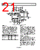
26 / 29 page  Data Sheet ADL5902 Rev. B | Page 25 of 28 HIGH FREQUENCY PERFORMANCE The ADL5902 is specified to 6 GHz; however, operation is possible to as high as 9 GHz with sufficient dynamic range for many purposes. Figure 52 shows the typical VOUT response and conformance error at 7 GHz, 8 GHz, and 9 GHz. –6 –5 –4 –3 –2 –1 0 1 2 3 4 5 6 0 0.25 0.50 0.75 1.00 1.25 1.50 1.75 2.00 2.25 2.50 2.75 3.00 –50 –40 –30 –20 –10 0 10 7GHz 8GHz 9GHz PIN (dBm) Figure 52. Typical VOUT and Log Conformance Error at 7 GHz, 8 GHz, and 9 GHz, 25°C Only LOW FREQUENCY PERFORMANCE The lowest frequency of operation of the ADL5902 is approxi- mately 50 MHz. This is the result of the circuit design and architecture of the ADL5902. DESCRIPTION OF CHARACTERIZATION The general hardware configuration used for most of the ADL5902 characterization is shown in Figure 53. The ADL5902 was driven in a single-ended configuration for most characterization, except where noted. Much of the data was taken using an Agilent E4438C signal source as a RF input stimulus. Several ADL5902 devices mounted on circuit boards constructed of Rodgers 3006 material are put into a test chamber simultaneously, and a Keithley S46 RF switching network connected the signal source to the appropriate device under test. The test chamber temperature was set to cycle over the appropriate temperature range. The signal source, switching, and chamber temperature are all controlled by a PC running Agilent VEE Pro. The subsequent response to stimulus was measured with a voltmeter and the results stored in a database for analysis later. In this way, multiple ADL5902 devices are characterized over amplitude, frequency, and temperature in a minimum amount of time. The RF stimulus amplitude was calibrated up to the circuit board that carries the ADL5902, and, thus, it does not account for the slight losses due to the connector on the circuit board that carries the ADL5902 nor for the loss of traces on the circuit board. For this reason, there is a small absolute amplitude error (generally <0.5 dB) not accounted for in the characterization data, but this is generally not important because the ADL5902 relative accuracy is unaffected. ADL5902 CHARACTERIZ ATION BOARD – TEST SITE 1 ADL5902 CHARACTERIZ ATION BOARD – TEST SITE 2 KEITHLEY S46 MICROWAVE SWITCH AGILENT E8251A MICROWAVE SIGNAL GENERATOR AGILENT 34980A SWITCH MATRIX/ DC METER AGILENT E3631A DC POWER SUPPLIES PERSONAL COMPUTER ADL5902 CHARACTERIZ ATION BOARD – TEST SITE 3 RF DC DATA AND CONTROL Figure 53. General Characterization Configuration |
|
|
链接网址 |
| ALLDATASHEET是否为您带来帮助? [ DONATE ] |
关于 Alldatasheet | 广告服务 | 联系我们 | 隐私政策 | 数据表链接 | 链接交换 | 制造商名单 All Rights Reserved©Alldatasheet.com |
| Russian : Alldatasheetru.com | Korean : Alldatasheet.co.kr | Spanish : Alldatasheet.es | French : Alldatasheet.fr | Italian : Alldatasheetit.com Portuguese : Alldatasheetpt.com | Polish : Alldatasheet.pl | Vietnamese : Alldatasheet.vn Indian : Alldatasheet.in | Mexican : Alldatasheet.com.mx | British : Alldatasheet.co.uk | New Zealand : Alldatasheet.co.nz |
|
Family Site : ic2ic.com |
icmetro.com |
 Chinese ▼
 English
 Chinese
 German
 Japanese
 Russian
 Korean
 Spanish
 French
 Italian
 Portuguese
 Polish
 Vietnamese
 Indian
 Mexican
 British
 New Zealand