|
数据搜索系统,热门电子元器件搜索 |
|
|
数据搜索系统,热门电子元器件搜索 |
|
MAX8559ETAII 数据表(PDF) 6 Page - Maxim Integrated Products |
|
|
|||||||||||||||||||||||||||||
MAX8559ETAII 数据表(HTML) 6 Page - Maxim Integrated Products |
|
|
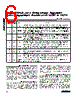
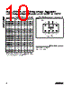
6 / 12 page  Detailed Description The MAX8559 is a dual, low-noise, low-dropout, low-qui- escent-current linear regulator designed primarily for battery-powered applications. The regulators are avail- able with preset 1.5V to 3.3V output voltages. These out- puts can supply loads up to 300mA with a 4.7µF output capacitor, or up to 150mA with a 2.2µF output capacitor. As illustrated in the Functional Diagram, the MAX8559 consists of a 1.25V reference, error amplifiers, P-chan- nel pass transistors, internal feedback voltage-dividers, and autodischarge circuitry. Feedback Control Loop The 1.25V bandgap reference is connected to the error amplifier’s inverting input. The error amplifier compares this reference with the feedback voltage and amplifies the difference. If the feedback voltage is lower than the reference voltage, the pass-transistor gate is pulled lower, allowing more current to pass to the output and increasing the output voltage. If the feedback voltage is too high, the pass-transistor gate is pulled up, allowing less current to pass to the output. The output voltage is fed back through an internal resistor voltage-divider connected to OUT_. Internal P-Channel Pass Transistor The MAX8559 features two 0.6Ω P-channel MOSFET pass transistors. A P-channel MOSFET provides sever- al advantages over similar designs using PNP pass transistors, including longer battery life. It requires no base drive, reducing quiescent current considerably. PNP-based regulators waste considerable current in dropout when the pass transistor saturates, and they also use high base-drive currents under large loads. The MAX8559 does not suffer from these problems, and with both outputs on it only consumes 180µA of Dual, 300mA, Low-Noise Linear Regulator with Independent Shutdown in UCSP or TDFN 6 _______________________________________________________________________________________ Pin Description PIN TDFN UCSP NAME FUNCTION 1A1 INA LDO A Regulator Input. Connect to INB. Input voltage can range from 2.5V to 6.5V. Bypass INA with a ceramic capacitor to GND (see the Capacitor Selection and Regulator Stability section). 2A2 SHDNA Shutdown A Input. A logic-low on SHDNA shuts down regulator A. If SHDNA and SHDNB are both low, both regulators and the internal reference are off and the supply current is reduced to 10nA (typ). If either SHDNA or SHDNB is a logic high, the internal reference is on. Connect SHDNA to INA for always-on operation of regulator A. 3A3 SHDNB Shutdown B Input. A logic-low on SHDNB shuts down regulator B. If SHDNA and SHDNB are both low, both regulators and the internal reference are off and the supply current is reduced to 10nA (typ). If either SHDNA or SHDNB is a logic high, the internal reference is on. Connect SHDNB to INB for always-on operation of regulator B. 4A4 INB LDO B Regulator Input. Connect to INA. Input voltage can range from 2.5V to 6.5V. Bypass INB with a ceramic capacitor to GND (see the Capacitor Selection and Regulator Stability section). 5B4 OUTB Regulator B Output. OUTB can source up to 300mA continuous current. Bypass OUTB with a ceramic capacitor to GND (see the Capacitor Selection and Regulator Stability section). During shutdown, OUTB is internally discharged to GND through a 385 Ω resistor. 6B3 GND Ground 7B2 BP Reference Noise Bypass. Bypass BP with a low-leakage 0.01µF ceramic capacitor for reduced noise at both outputs. 8B1 OUTA Regulator A Output. OUTA can source up to 300mA continuous current. Bypass OUTA with a ceramic capacitor to GND (see the Capacitor Selection and Regulator Stability section). During shutdown, OUTB is internally discharged to GND through a 385 Ω resistor. EP — Exposed Paddle Connect to ground plane. EP also functions as a heatsink. Solder to the circuit-board ground plane to maximize thermal dissipation. |
|
|
链接网址 |
| ALLDATASHEET是否为您带来帮助? [ DONATE ] |
关于 Alldatasheet | 广告服务 | 联系我们 | 隐私政策 | 数据表链接 | 链接交换 | 制造商名单 All Rights Reserved©Alldatasheet.com |
| Russian : Alldatasheetru.com | Korean : Alldatasheet.co.kr | Spanish : Alldatasheet.es | French : Alldatasheet.fr | Italian : Alldatasheetit.com Portuguese : Alldatasheetpt.com | Polish : Alldatasheet.pl | Vietnamese : Alldatasheet.vn Indian : Alldatasheet.in | Mexican : Alldatasheet.com.mx | British : Alldatasheet.co.uk | New Zealand : Alldatasheet.co.nz |
|
Family Site : ic2ic.com |
icmetro.com |
 Chinese ▼
 English
 Chinese
 German
 Japanese
 Russian
 Korean
 Spanish
 French
 Italian
 Portuguese
 Polish
 Vietnamese
 Indian
 Mexican
 British
 New Zealand