|
数据搜索系统,热门电子元器件搜索 |
|
|
数据搜索系统,热门电子元器件搜索 |
|
AD5228BUJZ100-R2 数据表(PDF) 12 Page - Analog Devices |
|
|
|||||||||||||||||||||||||||||
AD5228BUJZ100-R2 数据表(HTML) 12 Page - Analog Devices |
|
|
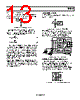
12 / 20 page  AD5228 Rev. 0 | Page 12 of 20 If the PU button is held for longer than 1 second, continuously holding it activates autoscan mode such that the AD5228 increments by four RWB steps per second (see Figure 3). Whenever the maximum RWB (= RAB) is reached, RWB stops incrementing regardless of the state of the PU pin. Any continu- ous holding of the PU pin to logic-low simply elevates the supply current. When both PU and PD buttons are pressed, RWB decrements until it stops at zero scale. All the preceding descriptions apply to PD operation. Due to the tolerance of the internal RC oscillator, all the timing information given previously is based on the typical values, which can vary ±30%. The AD5228 debouncer is carefully designed to handle common pushbutton tactile switches. Other switches that have excessive bounces and duration are not suitable to use in conjunction with the AD5228. B W A D0 D2 D1 D4 D3 RS RS = RAB/32 RW RS RS RS RDAC UP/DOWN CTRL AND DECODE Figure 34. AD5228 Equivalent RDAC Circuit PROGRAMMING THE DIGITAL POTENTIOMETERS Rheostat Operation If only the W-to-B or W-to-A terminals are used as variable resistors, the unused terminal can be opened or shorted with W. Such operation is called rheostat mode and is shown in Figure 35. A W B A W B A W B Figure 35. Rheostat Mode Configuration The end-to-end resistance, RAB, has 32 contact points accessed by the wiper terminal, plus the B terminal contact if RWB is used. Pushing the PU pin discretely increments RWB by one step. The total resistance becomes RS + RW as shown in Figure 34. The change of RWB can be determined by the number of discrete PU executions provided that its maximum setting is not reached during operation. ∆RWB can, therefore, be approximated as ⎟ ⎠ ⎞ ⎜ ⎝ ⎛ + + = ∆ W AB WB R R PU R 32 (1) ⎟ ⎠ ⎞ ⎜ ⎝ ⎛ + − = ∆ W AB WB R R PD R 32 (2) where: PU is the number of push-up executions. PD is the number of push-down executions. RAB is the end-to-end resistance. RW is the wiper resistance contributed by the on-resistance of the internal switch. Similar to the mechanical potentiometer, the resistance of the RDAC between the Wiper W and Terminal A also produces a complementary resistance, RWA. When these terminals are used, the B terminal can be opened or shorted to W. RWA can also be approximated if its maximum and minimum settings are not reached. ( ) ⎟ ⎠ ⎞ ⎜ ⎝ ⎛ + − − = ∆ W AB WA R R PU R 32 32 3) ( ) ⎟ ⎠ ⎞ ⎜ ⎝ ⎛ + − + = ∆ W AB WA R R PD R 32 32 (4) Note that Equations 1 to 4 do not apply when PU and PD = 0 execution. Because in the lowest end of the resistor string, a finite wiper resistance is present, care should be taken to limit the current flow between W and B in this state to a maximum pulse current of no more than 20 mA. Otherwise, degradation or possible destruction of the internal switches can occur. The typical distribution of the resistance tolerance from device to device is process lot dependent, and ±20% tolerance is possible. |
|
|
链接网址 |
| ALLDATASHEET是否为您带来帮助? [ DONATE ] |
关于 Alldatasheet | 广告服务 | 联系我们 | 隐私政策 | 数据表链接 | 链接交换 | 制造商名单 All Rights Reserved©Alldatasheet.com |
| Russian : Alldatasheetru.com | Korean : Alldatasheet.co.kr | Spanish : Alldatasheet.es | French : Alldatasheet.fr | Italian : Alldatasheetit.com Portuguese : Alldatasheetpt.com | Polish : Alldatasheet.pl | Vietnamese : Alldatasheet.vn Indian : Alldatasheet.in | Mexican : Alldatasheet.com.mx | British : Alldatasheet.co.uk | New Zealand : Alldatasheet.co.nz |
|
Family Site : ic2ic.com |
icmetro.com |
 Chinese ▼
 English
 Chinese
 German
 Japanese
 Russian
 Korean
 Spanish
 French
 Italian
 Portuguese
 Polish
 Vietnamese
 Indian
 Mexican
 British
 New Zealand