|
数据搜索系统,热门电子元器件搜索 |
|
|
数据搜索系统,热门电子元器件搜索 |
|
INMP621ACEZ-R7 数据表(PDF) 17 Page - TDK Electronics |
|
|
|||||||||||||||||||||||||||||
INMP621ACEZ-R7 数据表(HTML) 17 Page - TDK Electronics |
|
|
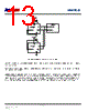
17 / 20 page  INMP621 ALTERNATIVE PCB LAND PATTERNS The standard PCB land pattern of the INMP621 has a solid rectangle around the edge of the footprint that can make routing the microphone signals more difficult in some board designs. This rectangle is used to improve the radio frequency (RF) immunity performance of the INMP621; however, it is not necessary to have this full rectangle connected for electrical functionality. If a design can tolerate reduced RF immunity, this rectangle can either be broken or removed completely from the PCB footprint. Figure 18 shows an example PCB land pattern with no enclosing rectangle around the edge of the part, and Figure 19 shows an example PCB land pattern with the rectangle broken on two sides so that the inner pads can be more easily routed on the PCB. Figure 18. Example PCB Land Pattern with No Enclosing Rectangle Figure 19. Example PCB Land Pattern with Broken Enclosing Rectangle Note that in both of these patterns, the solid ring around the sound port is still present; this ring is needed to ground the microphone and for acoustic performance. The pad on the package connected to this ring is ground and still needs a solid electrical connection to the PCB ground. If a pattern like one of these two examples is used on a PCB, take care that the unconnected rectangle on the bottom of the INMP621 is not placed directly over any exposed copper. This ring on the microphone is still at ground, and any PCB traces routed underneath it must be properly masked to avoid short circuits. . PCB MATERIAL AND THICKNESS The performance of the INMP621 is not affected by PCB thickness and can be mounted on either a rigid or flexible PCB. A flexible PCB with the microphone can be attached directly to the device housing with an adhesive layer. This mounting method offers a reliable seal around the sound port, while providing the shortest acoustic path for good sound quality. Page 17 of 20 Document Number: DS-INMP621-00 Revision: 1.0 Rev Date: 02/06/2014 |
|
|
链接网址 |
| ALLDATASHEET是否为您带来帮助? [ DONATE ] |
关于 Alldatasheet | 广告服务 | 联系我们 | 隐私政策 | 数据表链接 | 链接交换 | 制造商名单 All Rights Reserved©Alldatasheet.com |
| Russian : Alldatasheetru.com | Korean : Alldatasheet.co.kr | Spanish : Alldatasheet.es | French : Alldatasheet.fr | Italian : Alldatasheetit.com Portuguese : Alldatasheetpt.com | Polish : Alldatasheet.pl | Vietnamese : Alldatasheet.vn Indian : Alldatasheet.in | Mexican : Alldatasheet.com.mx | British : Alldatasheet.co.uk | New Zealand : Alldatasheet.co.nz |
|
Family Site : ic2ic.com |
icmetro.com |
 Chinese ▼
 English
 Chinese
 German
 Japanese
 Russian
 Korean
 Spanish
 French
 Italian
 Portuguese
 Polish
 Vietnamese
 Indian
 Mexican
 British
 New Zealand