|
数据搜索系统,热门电子元器件搜索 |
|
|
数据搜索系统,热门电子元器件搜索 |
|
INMP621ACEZ-R7 数据表(PDF) 10 Page - TDK Electronics |
|
|
|||||||||||||||||||||||||||||
INMP621ACEZ-R7 数据表(HTML) 10 Page - TDK Electronics |
|
|
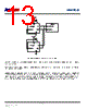
10 / 20 page  INMP621 THEORY OF OPERATION PDM DATA FORMAT The output from the DATA pin of the INMP621 is in pulse density modulated (PDM) format. This data is the 1-bit output of a fourth- order Σ-Δ modulator. The data is encoded so that the left channel is clocked on the falling edge of CLK, and the right channel is clocked on the rising edge of CLK. After driving the DATA signal high or low in the appropriate half frame of the CLK signal, the DATA driver of the microphone tristates. In this way, two microphones, one set to the left channel and the other to the right, can drive a single DATA line. See Figure 1 for a timing diagram of the PDM data format; the DATA1 and DATA2 lines shown in this figure are two halves of the single physical DATA signal. Figure 10 shows a diagram of the two stereo channels sharing a common DATA line. Figure 10. Stereo PDM Format If only one microphone is connected to the DATA signal, the output is only clocked on a single edge (Figure 11). For example, a left channel microphone is never clocked on the rising edge of CLK. In a single microphone application, each bit of the DATA signal is typically held for the full CLK period until the next transition because the leakage of the DATA line is not enough to discharge the line while the driver is tristated. Figure 11. Mono PDM Format See Table 6 for the channel assignments according to the logic level on the L/R SELECT pin. TABLE 6. INMP621 CHANNEL SETTING DATA2 (L) DATA2 (L) DATA1 (R) DATA1 (R) CLK DATA DATA1 (R) DATA1 (R) DATA1 (R) CLK DATA L/R SELECT Pin Setting Channel Low (tie to GND) Right (DATA1) High (tie to VDD) Left (DATA2) Page 10 of 20 Document Number: DS-INMP621-00 Revision: 1.0. Rev Date: 02/06/2014 |
|
|
链接网址 |
| ALLDATASHEET是否为您带来帮助? [ DONATE ] |
关于 Alldatasheet | 广告服务 | 联系我们 | 隐私政策 | 数据表链接 | 链接交换 | 制造商名单 All Rights Reserved©Alldatasheet.com |
| Russian : Alldatasheetru.com | Korean : Alldatasheet.co.kr | Spanish : Alldatasheet.es | French : Alldatasheet.fr | Italian : Alldatasheetit.com Portuguese : Alldatasheetpt.com | Polish : Alldatasheet.pl | Vietnamese : Alldatasheet.vn Indian : Alldatasheet.in | Mexican : Alldatasheet.com.mx | British : Alldatasheet.co.uk | New Zealand : Alldatasheet.co.nz |
|
Family Site : ic2ic.com |
icmetro.com |
 Chinese ▼
 English
 Chinese
 German
 Japanese
 Russian
 Korean
 Spanish
 French
 Italian
 Portuguese
 Polish
 Vietnamese
 Indian
 Mexican
 British
 New Zealand