|
数据搜索系统,热门电子元器件搜索 |
|
|
数据搜索系统,热门电子元器件搜索 |
|
ADP2291ARMZ-R7 数据表(PDF) 10 Page - Analog Devices |
|
|
|||||||||||||||||||||||||||||
ADP2291ARMZ-R7 数据表(HTML) 10 Page - Analog Devices |
|
|
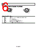
10 / 20 page  ADP2291 Rev. 0 | Page 10 of 20 THEORY OF OPERATION The ADP2291 is intended to charge a single cell, lithium battery from a supply voltage or wall adapter providing 4.5 V to 12 V. The charge controller adjusts the base current of an external PNP transistor to optimize current and voltage applied to the battery during charging. A low value resistor placed in series with the battery charging current provides current measure- ment for the ADP2291. To assure safety and long battery lifetime, the ADP2291 charges the battery using a simple step-by-step cycle, as shown in the state diagram of Figure 26. The normal charge cycle begins by measuring the battery voltage to determine charge level. If the battery is deeply discharged, then low current precharge is initiated. Once precharge is complete, normal fast charge at the maximum current (denoted as IMAX) begins. This maximum current can be adjusted by varying the sense resistor value or by varying the voltage at the adjust pin. As the battery approaches full capacity, the charging current is reduced until the end-of- charge condition is reached. Batteries that are not deeply discharged skip the precharge mode and immediately begin fast charging. Each of these modes and associated fault conditions are discussed in detail. PRECHARGE MODE For deeply-discharged cells, the ADP2291 charges at a reduced rate when the battery voltage VBAT < 2.8 V. This reduced rate is IMAX/10 when the ADJ pin voltage is 3 V, and IMAX/5 when the ADJ pin voltage is 1.5 V. For ADJ pin voltages in between, the charge current can be interpolated. If the battery voltage does not increase past 2.8 V before the precharge timer elapses (typically 30 minutes), a battery fault is assumed and the ADP2291 shuts down and does not restart until the input voltage is cycled OFF and then back ON. Note that in this mode shutdown commands are ignored. END-OF-CHARGE MODE Once the voltage loop reduces the charge current to 1/10 of its nominal value, IMAX (irrespective of the ADJ voltage), the ADP2291 detects the end-of-charge (EOC) state and the charge status indicator becomes high-impedance. Low level charging continues until the timer terminates the charge (nominally 30 minutes). SHUTDOWN MODE When the ADJ input is pulled below 0.4 V, the ADP2291 is put into shutdown mode. When in this mode, the charger is disabled, the current drawn from the battery falls to less than 1 µA and the current drawn from IN falls to 0.7 mA. When the charger is re-enabled, the charger returns to the START state but quickly sequences through the states until the proper charge mode is reached. CHARGE RESTART Once charge is complete in end-of-charge or timeout modes, the ADP2291 continually monitors the cell voltage and charge current. When the cell voltage falls by 100 mV or the charge current increases beyond the EOC hysteresis, the ADP2291 initiates another charge cycle to keep the cell fully charged. See the state diagram in Figure 26. PROGRAMMABLE TIMER The on-chip timer, controlled by an external capacitor CTIMER, determines the timeout intervals of the various charger modes. For example, a CTIMER value of 0.1 µF results in a precharge timeout interval of 30 minutes, a fast charge timeout of 3 hours, and an end-of-charge timeout of 30 minutes. The ratio between precharge and end-of-charge to fast charge time-out is always 1/6. All these time intervals are proportional to the CTIMER capacitor value, allowing them to be adjusted over a wide range. Connecting the TIMER pin to ground disables the timer. CHARGE STATUS INDICATOR The ADP2291 contains a charge status output, CHG, that sinks current when the ADP2291 is charging the battery. This output can be used as a visual signal by connecting it to an LED, or it may be used to generate a logic-level charge status signal by connecting a resistor between CHG and logic high. AUTOMATIC REVERSE ISOLATION When the voltage on the BAT pin is higher than the voltage on IN, the ADP2291 automatically connects the base of the pass device to BAT. This removes the necessity of having an external diode between the pass device and battery, further reducing the charger’s footprint and component count. OVERSHOOT PROTECTION In the event of a battery disconnect during charging, a voltage overshoot condition on BAT could occur. The ADP2291 includes an overshoot protection circuit that activates when VBAT rises to 5 V and sinks up to 1.5 A to protect the external components. POWER SUPPLY CHECKS To assure proper operation, the ADP2291 checks the absolute voltage level of the input supply and the supply voltage relative to the battery. When the supply IN is below 3.8 V, the chip is internally powered down and does not respond to external control. In this power-down mode, the device draws less than 1 µA from the battery. The VIN good comparator halts operation if the supply voltage is less than 165 mV above the battery voltage, insuring that charging only occurs if the supply voltage is sufficient. |
|
|
链接网址 |
| ALLDATASHEET是否为您带来帮助? [ DONATE ] |
关于 Alldatasheet | 广告服务 | 联系我们 | 隐私政策 | 数据表链接 | 链接交换 | 制造商名单 All Rights Reserved©Alldatasheet.com |
| Russian : Alldatasheetru.com | Korean : Alldatasheet.co.kr | Spanish : Alldatasheet.es | French : Alldatasheet.fr | Italian : Alldatasheetit.com Portuguese : Alldatasheetpt.com | Polish : Alldatasheet.pl | Vietnamese : Alldatasheet.vn Indian : Alldatasheet.in | Mexican : Alldatasheet.com.mx | British : Alldatasheet.co.uk | New Zealand : Alldatasheet.co.nz |
|
Family Site : ic2ic.com |
icmetro.com |
 Chinese ▼
 English
 Chinese
 German
 Japanese
 Russian
 Korean
 Spanish
 French
 Italian
 Portuguese
 Polish
 Vietnamese
 Indian
 Mexican
 British
 New Zealand