|
数据搜索系统,热门电子元器件搜索 |
|
|
数据搜索系统,热门电子元器件搜索 |
|
AD8099ACP-R2 数据表(PDF) 15 Page - Analog Devices |
|
|
|||||||||||||||||||||||||||||
AD8099ACP-R2 数据表(HTML) 15 Page - Analog Devices |
|
|
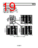
15 / 28 page  AD8099 Rev. B | Page 15 of 28 THEORY OF OPERATION The AD8099 is a voltage feedback op amp that employs a new highly linear low noise input stage. With this input stage, the AD8099 can achieve better than 90 dB distortion for a 2 V p-p, 10 MHz output signal with an input referred voltage noise of less than 1 nV/√Hz. This noise level and distortion performance has been previously achievable only with fully uncompensated amplifiers. The AD8099 achieves this level of performance for gains as low as +2. This new input stage also triples the achievable slew rate for comparably compensated 1 nV/√Hz amplifiers. The simplified AD8099 topology is shown in Figure 58. The amplifier is a single gain stage with a unity gain output buffer fabricated in Analog Devices’ extra fast complimentary bipolar process (XFCB). The AD8099 has 85 dB of open-loop gain and maintains precision specifications such as CMRR, PSRR, VOS, and ∆VOS/∆T to levels that are normally associated with topologies having two or more gain stages. BUFFER gm CC R1 RL VOUT Figure 58. AD8099 Topology The AD8099 can be externally compensated down to a gain of 2 through the use of an RC network. Above gains of 15, no exter- nal compensation network is required. To realize the full gain bandwidth product of the AD8099, no PCB trace should be connected to or within close proximity of the external compen- sation pin for the lowest possible capacitance. External compensation allows the user to optimize the closed- loop response for minimal peaking while increasing the gain bandwidth product in higher gains, lowering distortion errors that are normally more prominent with internally compensated parts in higher gains. For a fixed gain bandwidth, wideband distortion products would normally increase by 6 dB going from a closed-loop gain of 2 to 4. Increasing the gain bandwidth product of the AD8099 eliminates this effect with increasing closed-loop gain. The AD8099 is available in both a SOIC and an LFCSP, each of which has a thermal pad for lower operating temperature. To help avoid this pad in board layout, both packages have an extra output pin on the opposite side of the package for ease in con- necting a feedback network to the inputs. The secondary output pin also isolates the interaction of any capacitive load on the output and self-inductance of the package and bond wire from the feedback loop. While using the secondary output for feed- back, inductance in the primary output will now help to isolate capacitive loads from the output impedance of the amplifier. Since the SOIC has greater inductance in its output, the SOIC will drive capacitive loads better than the LFCSP. Using the primary output for feedback with both packages will result in the LFCSP driving capacitive load better than the SOIC. The LFCSP and SOIC pinouts are identical, except for the rotation of all pins counterclockwise by one pin on the LFCSP. This isolates the inputs from the negative power supply pin, removing a mutually inductive coupling that is most prominent while driving heavy loads. For this reason, the LFCSP second harmonic, while driving a heavy load, is significantly better than that of the SOIC. A three-state input pin is provided on the AD8099 for a high impedance power-down and an optional input bias current cancellation circuit. The high impedance output allows several AD8099s to drive the same ADC or output line time inter- leaved. Pulling the DISABLE pin low activates the high impedance state. See Table 5 for threshold levels. When the DISABLE pin is left floating, the AD8099 operates normally. With the DISABLE pin pulled within 0.7 V of the positive supply, an optional input bias current cancellation circuit is turned on, which lowers the input bias current to less than 200 nA. In this mode, the user can drive the AD8099 with a high dc source impedance and still maintain minimal output referred offset without having to use impedance matching techniques. In addition, the AD8099 can be ac-coupled while setting the bias point on the input with a high dc impedance network. The input bias current cancellation circuit will double the input referred current noise, but this effect is minimal as long as wideband impedance is kept low (see Figure 48 and Figure 51). A pair of internally connected diodes limits the differential voltage between the noninverting input and the inverting input of the AD8099. Each set of diodes has two series diodes, which are connected in anti-parallel. This limits the differential voltage between the inputs to approximately ±1.8 V. All of the AD8099 pins are ESD protected with voltage limiting diodes connected between both rails. The protection diodes can handle 5 mA of steady state current. Currents should be limited to 5 mA or less through the use of a series limiting resistor. |
|
|
链接网址 |
| ALLDATASHEET是否为您带来帮助? [ DONATE ] |
关于 Alldatasheet | 广告服务 | 联系我们 | 隐私政策 | 数据表链接 | 链接交换 | 制造商名单 All Rights Reserved©Alldatasheet.com |
| Russian : Alldatasheetru.com | Korean : Alldatasheet.co.kr | Spanish : Alldatasheet.es | French : Alldatasheet.fr | Italian : Alldatasheetit.com Portuguese : Alldatasheetpt.com | Polish : Alldatasheet.pl | Vietnamese : Alldatasheet.vn Indian : Alldatasheet.in | Mexican : Alldatasheet.com.mx | British : Alldatasheet.co.uk | New Zealand : Alldatasheet.co.nz |
|
Family Site : ic2ic.com |
icmetro.com |
 Chinese ▼
 English
 Chinese
 German
 Japanese
 Russian
 Korean
 Spanish
 French
 Italian
 Portuguese
 Polish
 Vietnamese
 Indian
 Mexican
 British
 New Zealand