|
数据搜索系统,热门电子元器件搜索 |
|
|
数据搜索系统,热门电子元器件搜索 |
|
ADAR2001ACCZ-R7 数据表(PDF) 18 Page - Analog Devices |
|
|
|||||||||||||||||||||||||||||
ADAR2001ACCZ-R7 数据表(HTML) 18 Page - Analog Devices |
|
|
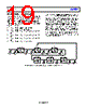
18 / 39 page  ADAR2001 Data Sheet Rev. 0 | Page 18 of 39 TRANSMITTER STATE MACHINE Like the multiplier/filter state machine, the transmitter state machine can be used to quickly cycle through transmit states without using the comparatively slower SPI interface. To enable the state machine, set the TX_SEQ_EN bit (Register 0x016, Bit 7) high. The transmitter state machine controls the status of the four PAs (sleep, ready, or active) and the status of the 1:4 splitter network by defining the desired modes of operation in Register 0x050 to Register 0x06F. The PAs are in sleep mode when the ready and active bits are not enabled. Each mode outlines a custom set of operating conditions. Although only four states are required to cycle through a transmit cycle by each of the PAs, a state machine depth of 70 is provided for optimum flexibility and to lower the total number of control lines required to operate multiple ADAR2001 chips in parallel. It is possible to control up to 16 ADAR2001 ICs using the same four sequencer lines (MADV, MRST, TxADV, TxRST). See the Sequencer Control Latch Bypass section for more information. Following the mode definitions, the user must fill the state bits in Register 0x019 to Register 0x03B with the modes of interest. Any state can point to any mode, except State 0 which always points to Mode 0. Note that the sequencer moves through the states in order, up to the state machine depth. After the states are defined, the user must set the number of states to be used by the sequencer by changing the TX_STATES bits (Register 0x017, Bits[6:0]). TX_STATES is 0 indexed. Therefore, setting the depth to 0 leaves TX_STATE_1 (Register 0x019, Bits[7:4]) as the only state in the loop. After the transmit state machine is programmed, operation is controlled by the TxRST (transmit reset, Pin 9) and TxADV (transmit advance, Pin 8) pins. Alternatively, operation can be controlled through the SPI using the TX_RST_SPI and TX_ADV_SPI bits (Register 0x044, Bit 1 and Bit 0, respectively). TxRST moves the pointer on the transmit state machine to State 0 regardless of the current position of the pointer and can be asserted at any time. State 0 always refers to Mode 0 and cannot be set to another mode. However, Mode 0 can be overwritten with any transmitter configuration. Mode 0 is defined in Register 0x050 and Register 0x051. TxADV pulses advance the transmitter state machine pointer one state at a time until the defined sequencer depth is cycled through. At that point, an additional TxADV pulse moves the pointer back to State 1. State 1 applies the mode defined in the TX_STATE_1 bits (Register 0x019, Bits[7:4]). SINGLE-CHANNEL FREQUENCY SWEEP Figure 29 shows a method of operation that can be used during a 20 GHz to 40 GHz frequency sweep of Channel 1. Based on Table 7, three multiplier/filter states are required during a 20 GHz to 40 GHz sweep. In this example, the defined state machine depth, MULT_STATES (Register 0x018, Bits[3:0]), is 3 because there are four states inside the loop, and MULT_STATES is 0 indexed. As shown in Figure 29, • Multiplier/Filter State 0 = sleep (outside the loop) • Multiplier/Filter State 1 = mid band multiplier ready • Multiplier/Filter State 2 = output 20 GHz to 25 GHz to PAs • Multiplier/Filter State 3 = output 25 GHz to 30 GHz to PAs • Multiplier/Filter State 4 = output 30 GHz to 40 GHz to PAs The initial state is the sleep state where power consumption is at a minimum. This state is reached by pulsing the MRST pin. A pulse on MADV then advances the state machine to the first state inside the loop, which is defined as a ready state, where the mid band multiplier is partially powered but not active, and the BPF is disabled to pass the higher portion of the mid band. By using this ready state, an additional pulse on MADV makes this subcircuit path active in less than 10 ns. By making use of the ready mode for the upcoming state throughout the sweep, the multiplier/filter switching and settling time can be kept less than 10 ns between all states. After the appropriate number of pulses is applied to MADV (5, in this case), the state machine automatically returns to the first state in the loop (ready). MULT: ALL SLEEP BPF: N/A PA: ALL SLEEP SLEEP MULT_STATE_0 TX_STATE_0 MULT: MID RDY BPF: N/A PA: CH. 1 RDY CHANNEL 1 READY MULT_STATE_1 TX_STATE_1 MULT: MID ACT BPF: HIGH PA: CH. 1 ACT CHANNEL 1 20GHz TO 25GHz MULT_STATE_2 TX_STATE_2 MULT: HIGH ACT BPF: LOW PA: CH. 1 ACT CHANNEL 1 25GHz TO 30GHz MULT_STATE_3 TX_STATE_2 MULT: HIGH ACT BPF: HIGH PA: CH. 1 ACT CHANNEL 1 30GHz TO 40GHz MULT_STATE_4 TX_STATE_2 MULTIPLIER RESET TRANSMITTER RESET MULTIPLIER ADVANCE TRANSMITTER ADVANCE MULTIPLIER ADVANCE TRANSMITTER ADVANCE MULTIPLIER ADVANCE MULTIPLIER ADVANCE TRANSMITTER ADVANCE MULTIPLIER ADVANCE Figure 29. State Machine Loop Example for a Frequency Sweep from 20 GHz to 40 GHz on a Single Channel |
|
链接网址 |
| ALLDATASHEET是否为您带来帮助? [ DONATE ] |
关于 Alldatasheet | 广告服务 | 联系我们 | 隐私政策 | 数据表链接 | 链接交换 | 制造商名单 All Rights Reserved©Alldatasheet.com |
| Russian : Alldatasheetru.com | Korean : Alldatasheet.co.kr | Spanish : Alldatasheet.es | French : Alldatasheet.fr | Italian : Alldatasheetit.com Portuguese : Alldatasheetpt.com | Polish : Alldatasheet.pl | Vietnamese : Alldatasheet.vn Indian : Alldatasheet.in | Mexican : Alldatasheet.com.mx | British : Alldatasheet.co.uk | New Zealand : Alldatasheet.co.nz |
|
Family Site : ic2ic.com |
icmetro.com |
 Chinese ▼
 English
 Chinese
 German
 Japanese
 Russian
 Korean
 Spanish
 French
 Italian
 Portuguese
 Polish
 Vietnamese
 Indian
 Mexican
 British
 New Zealand