|
数据搜索系统,热门电子元器件搜索 |
|
|
数据搜索系统,热门电子元器件搜索 |
|
KS2V2-61-R 数据表(PDF) 2 Page - M-System Co.,Ltd. |
|
|
|||||||||||||||||||||||||||||
KS2V2-61-R 数据表(HTML) 2 Page - M-System Co.,Ltd. |
|
|
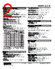
2 / 4 page  MODEL: KS2V2 KS2V2 SPECIFICATIONS ES-3608 Rev.10 Page 2/4 https://www.m-system.co.jp/ GENERAL SPECIFICATIONS Construction: Panel flush mounting, plug-in Connection: M3.5 screw terminals Screw terminal: Chromated steel Housing material: Flame-resistant resin (gray) Isolation: Input to SET1 to SET2 to power Time constant for the input filter (P-dF): 0.0 to 900.0 sec. (0 – 63 %) Alarm relay switching delay time (P-d1, P-d2): 1 to 10 sec.; programmable independently for each setpoint Programming: Front key Setpoint adjustment (ST1, ST2): -5 to +105 %; programmable independently for each setpoint Deadband (hysteresis) (HYS1, HYS2): 0 – 102 %; programmable independently for each setpoint Burnout: Upscale (standard), downscale (available to change) Power ON delay (P-d0): 0 to 20 sec. Read rate: 0.5 sec. Alarm mode (P-A1, P-A2): Programmable independently for each setpoint; See Table below. Param. Code (P-A1) (P-A2) Alarm Modes Trip Operation Set Value Latching Hold* Relay & LED Behavior in Tripped Conditions 0 No alarm ---- ---- ---- 1 High Absolute value Without LED ON Coil energized 2 Low Absolute value Without LED ON Coil energized 3 High Absolute value With LED ON Coil energized 4 Low Absolute value With LED ON Coil energized 5 High Absolute value Without LED ON Coil de-energized 6 Low Absolute value Without LED ON Coil de-energized 7 High Absolute value With LED ON Coil de-energized 8 Low Absolute value With LED ON Coil de-energized *Without latching hold function, the unit is tripped upon starting operation when the unit is set to Low alarm. With the function, the unit is NOT tripped until the temperature goes once above and then below the setpoint. DISPLAY Display: 4 digits of 10 mm (.39”) height, 7-segment LED Scaling range: -1999 to 9999 counts Measured Value (PV)/Alarm (SET1) display: Red LEDs Alarm (SET2) parameter display: Green LEDs PV display at abnormal input: Over range or under range displayed Front LEDs Power indicator: Green LED turns on while the power is turned on. Measured Value (PV) indicator: Green LED turns on when PV display is set. Alarm SET1 indicator: Red LED turns on when the Alarm SET1 is in tripped conditions. Alarm SET2 Indicator: Red LED turns on when the Alarm SET2 is in tripped conditions. Engineering unit indication: Sticker label attached; DC, AC, W, °C, °F, V, mV, A, mA, %, kW, mW, kV, kA, kvar, Mvar, var, m, mm, kg, kg/h, kPa, MPa, N·m, Nm3/h, m3/h, m3/sec, m/sec, ℓ/min, %RH, ℓ, ℓ/h, t/h, rpm, ppm, pH, Pa. INPUT SPECIFICATIONS ■ DC Voltage: -5 – +105 % Input resistance: ≥ 1 MΩ OUTPUT SPECIFICATIONS ■ Relay Contact: SPDT relays 220 V AC @3 A (cos ø = 1) 30 V DC @3 A (resistive load) Caution: N.O. and N.C. contacts could be conductive at the same time. DO NOT connect both contacts at the same time. Maximum switching voltage: 220 V AC or 30 V DC Maximum switching power: 660 VA or 90 W Minimum load: 10 V DC @1 mA Mechanical life: 2 × 10⁷ cycles with no loads For maximum relay life with inductive loads, external protection is recommended. INSTALLATION Power consumption •AC: Approx. 3.1 VA at 100 V Approx. 4.1 VA at 200 V Approx. 4.8 VA at 264 V •DC: Approx. 1.7 W Operating temperature: -10 to +55°C (14 to 131°F) Operating humidity: 30 to 90 %RH (non-condensing) Mounting: Panel flush mounting with attached mounting bracket, surface or DIN rail Weight: 200 g (0.44 lb) PERFORMANCE Display accuracy: ±0.5% FS ±1 digit Setpoint accuracy: Display accuracy ± 0.1 % FS Trip point repeatability: Included in the setpoint accuracy Line voltage effect: Included in the display accuracy Insulation resistance: ≥ 100 MΩ with 500 V DC Dielectric strength: 1500 V AC @1 minute |
|
|
链接网址 |
| ALLDATASHEET是否为您带来帮助? [ DONATE ] |
关于 Alldatasheet | 广告服务 | 联系我们 | 隐私政策 | 数据表链接 | 链接交换 | 制造商名单 All Rights Reserved©Alldatasheet.com |
| Russian : Alldatasheetru.com | Korean : Alldatasheet.co.kr | Spanish : Alldatasheet.es | French : Alldatasheet.fr | Italian : Alldatasheetit.com Portuguese : Alldatasheetpt.com | Polish : Alldatasheet.pl | Vietnamese : Alldatasheet.vn Indian : Alldatasheet.in | Mexican : Alldatasheet.com.mx | British : Alldatasheet.co.uk | New Zealand : Alldatasheet.co.nz |
|
Family Site : ic2ic.com |
icmetro.com |
 Chinese ▼
 English
 Chinese
 German
 Japanese
 Russian
 Korean
 Spanish
 French
 Italian
 Portuguese
 Polish
 Vietnamese
 Indian
 Mexican
 British
 New Zealand