|
数据搜索系统,热门电子元器件搜索 |
|
|
数据搜索系统,热门电子元器件搜索 |
|
MXR-V2-R 数据表(PDF) 1 Page - M-System Co.,Ltd. |
|
|
|||||||||||||||||||||||||||||
MXR-V2-R 数据表(HTML) 1 Page - M-System Co.,Ltd. |
|
|
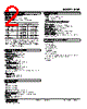
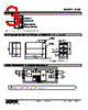
1 / 3 page  MODEL: MXR MXR SPECIFICATIONS ES-1714 Rev.11 Page 1/3 http://www.m-system.co.jp/ Plug-in Signal Conditioners MX-UNIT RTD TRANSMITTER (front configurable) Functions & Features • Converts an RTD input into a linearized process signal • Field-programmable RTD type, temperature and output range • Easy programming via front UP-DOWN keys with a help of 4-digit and 2-digit displays • I/O signal inversion feature • Isolation up to 2000 V AC • Loop test output • High-density mounting Typical Applications • Isolation between control room and field instrumentation • Ideal for quick spare part 50 (1.97) 123 (4.84) 80 (3.15) mm (inch) MODEL: MXR–[1]–[2][3] ORDERING INFORMATION • Code number: MXR-[1]-[2][3] Specify a code from below for each of [1] through [3]. (e.g. MXR-V1-M2/Q) • Specify the specification for option code /Q (e.g. /C01/S01/SET) [1] OUTPUT Current Z1: Range 0 – 20 mA DC (Load resistance 600Ω max.) Voltage V1: Range -1 – +1 V DC (Load resistance 1000Ω min.) V2: Range -10 – +10 V DC (Load resistance 10kΩ min.) [2] POWER INPUT AC Power M2: 100 – 240 V AC (Operational voltage range 85 – 264 V, 47 – 66 Hz) DC Power R: 24 V DC (Operational voltage range 24 V ±10 %, ripple 10 %p-p max.) P: 110 V DC (Operational voltage range 85 – 150 V, ripple 10 %p-p max.) [3] OPTIONS blank: none /Q: With options (specify the specification) SPECIFICATIONS OF OPTION: Q (multiple selections) COATING (For the detail, refer to M-System's web site.) /C01: Silicone coating /C02: Polyurethane coating /C03: Rubber coating TERMINAL SCREW MATERIAL /S01: Stainless steel EX-FACTORY SETTING /SET: Preset according to the Ordering Information Sheet (No. ESU-1714) GENERAL SPECIFICATIONS Construction: Plug-in Connection: M3.5 screw terminals Screw terminal: Chromated steel (standard) or stainless steel Housing material: Flame-resistant resin (black) Isolation: Input to output to power At burnout: Downscale ≤ -10 %, Upscale ≥ 110 %, Output ≤ 0 mA not available Programming: Via front keys • Input Type • Moving average • Burnout • etc. For detailed information, refer to the instruction manual. ■ DISPLAY LED: 8 mm (.31”) 7 segment, red Number of display digits: 4 digits for DATA display; 2 digits for ITEM display PV indication: Input signal in engineering unit Overrange indication: LEDs blinking Burnout indication: LEDs blinking and the PLC turns on. Power saving mode: Displays turn off if the keys are untouched for a preset time period LEDs: Red; the PL1 turns on with negative polarity and the PL2 turns on with burnout or programming error. |
类似零件编号 - MXR-V2-R |
|
类似说明 - MXR-V2-R |
|
|
|
链接网址 |
| ALLDATASHEET是否为您带来帮助? [ DONATE ] |
关于 Alldatasheet | 广告服务 | 联系我们 | 隐私政策 | 数据表链接 | 链接交换 | 制造商名单 All Rights Reserved©Alldatasheet.com |
| Russian : Alldatasheetru.com | Korean : Alldatasheet.co.kr | Spanish : Alldatasheet.es | French : Alldatasheet.fr | Italian : Alldatasheetit.com Portuguese : Alldatasheetpt.com | Polish : Alldatasheet.pl | Vietnamese : Alldatasheet.vn Indian : Alldatasheet.in | Mexican : Alldatasheet.com.mx | British : Alldatasheet.co.uk | New Zealand : Alldatasheet.co.nz |
|
Family Site : ic2ic.com |
icmetro.com |
 Chinese ▼
 English
 Chinese
 German
 Japanese
 Russian
 Korean
 Spanish
 French
 Italian
 Portuguese
 Polish
 Vietnamese
 Indian
 Mexican
 British
 New Zealand