|
数据搜索系统,热门电子元器件搜索 |
|
|
数据搜索系统,热门电子元器件搜索 |
|
R7D-YV2-R 数据表(PDF) 6 Page - M-System Co.,Ltd. |
|
|
|||||||||||||||||||||||||||||
R7D-YV2-R 数据表(HTML) 6 Page - M-System Co.,Ltd. |
|
|
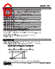
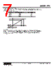
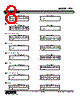
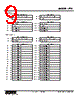
6 / 46 page  MODEL: R7C R7C SPECIFICATIONS ES-7801 Rev.26 Page 6/46 http://www.m-system.co.jp/ INDICATOR LED PWR ON ON ON ON ON ON ON ON ON ON ON ON ON ON ON ON ON ON OFF ■ STATUS INDICATOR LED OFF = OFF, ON = ON, BL = Blinking *1. SD LED may look not blinking but ON with high baud rate and fewer connected modules. *2. LEDs indicated with “----” in STATUS rarely occurs in normal operation. (LED failure or the like as possible cause). ■ DISCRETE I/O STATUS INDICATOR LED Discrete I/O modules, including those for extensions, have LED indicators showing I/O signal status. Totalized pulse modules have LED indicators showing input signal status. Contact ON : LED ON Contact OFF : LED OFF RUN ON ON ON ON ON ON ON ON ON OFF OFF OFF OFF OFF OFF OFF OFF OFF OFF ERR BL BL BL BL BL OFF OFF OFF OFF BL BL BL BL OFF OFF OFF OFF ON OFF SD* 1 BL BL BL OFF OFF BL BL OFF OFF BL BL OFF OFF BL BL OFF OFF OFF OFF RD ON ON OFF ON OFF ON OFF ON OFF ON OFF ON OFF ON OFF ON OFF ON/OFF OFF STATUS* 2 Communicates normally with occasional CRC errors due to noise interference. Communicates normally but the Baud Rate and/or Station Address switches failed. ERR LED blinks approximately in 0.5 seconds intervals. ---- CRC error found in the received data. Unable to respond. ---- Normal communication ---- Unable to receive data addressed to the station. ---- Performs the interval-timed responses but CRC error found in receiving the refresh data. ---- CRC error found in the data addressed to the station. ---- Link is not started. ---- No data addressed to the station. Or unable to receive data addressed to the station due to noise interference. (Missing parts of the data sent from the master) Unable to receive data due to wire breakdown Faulty Baud Rate and/or Station Address setting Power input removed. Or power supply failure. DATA CONVERSION I 0 – 100% DATA CONVERSION Analog input data is converted into digital representations of 0 – 100% proportional to each scaled range. The converted % values are multiplied by 100 and expressed in 16 bits. Overrange input is possible from -15 to +115% of the nominal range. When the signal exceeds the limit, the data is fixed at -15% or +115% respectively. Negative value is represented in 2 s complements. • Input Range 0 – 5 V DC ≤ -0.75 V 0 V 5 V ≥ 5.75 V Input Value -15% 0% 100% 115% Input % -1500 0 10000 11500 Converted Data, Decimal FA24 0 2710 2CEC Converted Data, Hex Analog output is converted in the reverse order of the input data. The output range 0 – 5 V DC is expressed as 10000 at 5.0 V (100%) and 0 at 0 V (0%). 11500 (2CEC) 10000 (2710) -0.75 -1500 (FA24) 5.0 5.75 0 (V) |
|
链接网址 |
| ALLDATASHEET是否为您带来帮助? [ DONATE ] |
关于 Alldatasheet | 广告服务 | 联系我们 | 隐私政策 | 数据表链接 | 链接交换 | 制造商名单 All Rights Reserved©Alldatasheet.com |
| Russian : Alldatasheetru.com | Korean : Alldatasheet.co.kr | Spanish : Alldatasheet.es | French : Alldatasheet.fr | Italian : Alldatasheetit.com Portuguese : Alldatasheetpt.com | Polish : Alldatasheet.pl | Vietnamese : Alldatasheet.vn Indian : Alldatasheet.in | Mexican : Alldatasheet.com.mx | British : Alldatasheet.co.uk | New Zealand : Alldatasheet.co.nz |
|
Family Site : ic2ic.com |
icmetro.com |
 Chinese ▼
 English
 Chinese
 German
 Japanese
 Russian
 Korean
 Spanish
 French
 Italian
 Portuguese
 Polish
 Vietnamese
 Indian
 Mexican
 British
 New Zealand