|
数据搜索系统,热门电子元器件搜索 |
|
|
数据搜索系统,热门电子元器件搜索 |
|
R80NECT1-R 数据表(PDF) 2 Page - M-System Co.,Ltd. |
|
|
|||||||||||||||||||||||||||||
R80NECT1-R 数据表(HTML) 2 Page - M-System Co.,Ltd. |
|
|
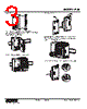
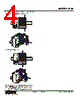
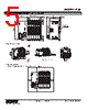
2 / 6 page  MODEL: R80 R80 SPECIFICATIONS ES-7021 Rev.0 Page 2/6 http://www.m-system.co.jp/ ·Power supply, exc. supply: Tension clamp terminal block (Front twin connection) Applicable wire size: 0.2 to 2.5 mm2, stripped length 10 mm ·EtherCAT: RJ-45 connector •I/O module: Tension clamp terminal block Applicable wire size: 0.2 to 1.5 mm2, stripped length 10 mm Housing material: Flame-resistant resin (black) Max. number of I/O modules: 16 (module address: 0 to 15) Internal communication bus: Transmission cycle approx. 65 μsec. + 65 μsec. x No. of Modules ■ Weight R80NECT1: 210 g (0.46 lb) R80DAT8A: 80 g (0.18 lb) R80DCT8A: 80 g (0.18 lb) Protective cover: 15 g (0.03 lb) CURRENT CONSUMPTION The I/O modules operate by the DC voltage (5 V DC) supplied from the power/network module. Arrange these modules in order that the total current consumed by these modules can be within the supply current capacity. If the current consumption exceeds the limit, change the combination of I/O modules or reduce the no. of modules mounted. Even if total consumption current of the I/O modules is less than the supply current capacity, the total install number of the modules is max. 16. ■ Max. current consumption R80DAT8A: 100 mA R80DCT8A: 120 mA USING EXCITATION SUPPLY Some I/O modules use excitation supply, on the other hand some I/O modules do not. When excitation supply is cut off during power supply is on, operation is as the table shown below. MODEL EXC. SUPPLY OPERATION AT ONLY EXC. SUPPLY CUTOFF R80DAT8A √ Input is turned OFF. R80DCT8A √ Output is turned OFF. ‘√’: Excitation supply is used. ‘–’: Excitation supply is not used. BASIC CONFIGURATION The number of I/O modules that can be mounted changes depending on the power/network module. Refer to the specifications of each power/network module for details. Althoug the module address can be arbitrarily set regardless of its mounting position, to avoid overlapped and unused addresses, set them consecutively starting at 0. Only for rightmost module, set termination resistor to enable. Protective cover is included in the package of power/network module. I/O MODULES POWER/NETWORK MODULE PROTECTIVE COVER HOW TO MOUNT THE MODULE ON DIN RAIL ■ • Power/Network Module Position the upper hook at the rear on the DIN rail and push in the lower. When removing the module, push down the DIN rail adaptor utilizing a flat-blade screwdriver and pull. Hook DIN Rail Adaptor |
|
|
链接网址 |
| ALLDATASHEET是否为您带来帮助? [ DONATE ] |
关于 Alldatasheet | 广告服务 | 联系我们 | 隐私政策 | 数据表链接 | 链接交换 | 制造商名单 All Rights Reserved©Alldatasheet.com |
| Russian : Alldatasheetru.com | Korean : Alldatasheet.co.kr | Spanish : Alldatasheet.es | French : Alldatasheet.fr | Italian : Alldatasheetit.com Portuguese : Alldatasheetpt.com | Polish : Alldatasheet.pl | Vietnamese : Alldatasheet.vn Indian : Alldatasheet.in | Mexican : Alldatasheet.com.mx | British : Alldatasheet.co.uk | New Zealand : Alldatasheet.co.nz |
|
Family Site : ic2ic.com |
icmetro.com |
 Chinese ▼
 English
 Chinese
 German
 Japanese
 Russian
 Korean
 Spanish
 French
 Italian
 Portuguese
 Polish
 Vietnamese
 Indian
 Mexican
 British
 New Zealand