|
数据搜索系统,热门电子元器件搜索 |
|
|
数据搜索系统,热门电子元器件搜索 |
|
AD8271ARMZ-R7 数据表(PDF) 18 Page - Analog Devices |
|
|
|||||||||||||||||||||||||||||
AD8271ARMZ-R7 数据表(HTML) 18 Page - Analog Devices |
|
|
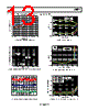
18 / 20 page  AD8271 Rev. 0 | Page 18 of 20 Many signal gains have more than one configuration choice, which allows freedom in choosing the op amp closed-loop gain. In general, for designs that need to be stable with a large capacitive load on the output, choose a configuration with high loop gain. Otherwise, choose a configuration with low loop gain, because these configurations typically have lower noise, lower offset, and higher bandwidth. The AD8271 Specifications section and Typical Performance Characteristics section show the performance of the part primarily when it is in the difference amplifier configuration. To estimate the performance of the part in a single-ended configuration, refer to the difference amplifier configuration with the corresponding closed-loop gain (see Table 10). Table 10. Closed-Loop Gain of the Difference Amplifiers Difference Amplifier Gain Closed-Loop Gain 0.5 1.5 1 2 2 3 Gain of 1 Configuration The AD8271 is designed to be stable for loop gains of 1.5 and greater. Because a typical voltage follower configuration has a loop gain of 1, it may be unstable. Several stable configurations for gain of 1 are listed in Table 9. KELVIN MEASUREMENT In the case where the output load is located remotely or at a distance from the AD8271, as shown in Figure 51, wire resistance can actually cause significant errors at the load. –IN 10k Ω 10k Ω 10k Ω 10k Ω +IN RW (WIRE RESISTANCE) RL 1k Ω Figure 51. Wire Resistance Causes Errors at Load Voltage Since the output of the AD8271 is not internally tied to any of the feedback resistors, Kelvin type measurements are possible because the op amp output and feedback can both be connected closer to the load (Figure 52). The Kelvin sensing on the feedback minimizes error at the load caused by voltage drops across the wire resistance. This technique is most effective in reducing errors for loads less than 10 kΩ. As the load resistance increases, the error due to the wire resistance becomes less significant. Because it adds the sense wire resistance to the feedback resistor, a trade-off of the Kelvin connection is that it can degrade common- mode rejection, especially over temperature. For sense wire resistance less than 1 Ω, it is typically not an issue. If common- mode performance is critical, two amplifier stages can be used: the first stage removes common-mode interference, and the second stage performs the Kelvin drive. 10k Ω Rw Rw SENSE FORCE –IN 10k Ω 10k Ω 10k Ω +IN RL 1k Ω Figure 52. Connecting Both the Output and Feedback at the Load Minimizes Error Due to Wire Resistance INSTRUMENTATION AMPLIFIER The AD8271 can be used as a building block for high performance instrumentation amplifiers. For example, Figure 53 shows how to build an ultralow noise instrumentation amplifier using the AD8599 dual op amp. External resistors RG and RFx provide gain; therefore, the output is () () 8271 2 1 AD G Fx IN IN OUT G R R V V V ⎟⎟ ⎠ ⎞ ⎜⎜ ⎝ ⎛ + − = − + –IN +IN 10k Ω 10k Ω 10k Ω 10k Ω REF AD8599 A2 AD8599 A2 RG 20 Ω RF1 RF2 2k Ω AD8271 OUT 2k Ω VS = ±15V Figure 53.Ultralow Noise Instrumentation Amplifier Using AD8599 Configured for Gain = 201 For optimal noise performance, it is desirable to have a high gain at the input stage using low value gain-setting resistors, as shown in this particular example. With less than 2 nV/√Hz input-referred noise (see Figure 54) at ~10 mA supply current, the AD8271 and AD8599 combination offers an in-amp with a fine balance of critical specifications: a gain bandwidth product of 10 MHz, low bias current, low offset drift, high CMRR, and high slew rate. 0 1.0 2.0 3.0 4.0 5.0 6.0 7.0 8.0 9.0 10.0 1 10 100 1k 10k 100k FREQUENCY (Hz) G = 201 BANDWIDTH LIMIT Figure 54. Ultralow Noise In-Amp Voltage Noise Spectral Density vs. Frequency, Referred to Input |
|
|
链接网址 |
| ALLDATASHEET是否为您带来帮助? [ DONATE ] |
关于 Alldatasheet | 广告服务 | 联系我们 | 隐私政策 | 数据表链接 | 链接交换 | 制造商名单 All Rights Reserved©Alldatasheet.com |
| Russian : Alldatasheetru.com | Korean : Alldatasheet.co.kr | Spanish : Alldatasheet.es | French : Alldatasheet.fr | Italian : Alldatasheetit.com Portuguese : Alldatasheetpt.com | Polish : Alldatasheet.pl | Vietnamese : Alldatasheet.vn Indian : Alldatasheet.in | Mexican : Alldatasheet.com.mx | British : Alldatasheet.co.uk | New Zealand : Alldatasheet.co.nz |
|
Family Site : ic2ic.com |
icmetro.com |
 Chinese ▼
 English
 Chinese
 German
 Japanese
 Russian
 Korean
 Spanish
 French
 Italian
 Portuguese
 Polish
 Vietnamese
 Indian
 Mexican
 British
 New Zealand