|
数据搜索系统,热门电子元器件搜索 |
|
|
数据搜索系统,热门电子元器件搜索 |
|
STDRIVE601 数据表(PDF) 14 Page - STMicroelectronics |
|
|
|||||||||||||||||||||||||||||
STDRIVE601 数据表(HTML) 14 Page - STMicroelectronics |
|
|
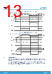
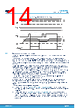
14 / 26 page  Figure 8. VBO power-ON and UVLO timing VCC VCCthON VCCthOFF 0 V 0 V FAULT HIN HVG-OUT BOthON VBOthOFF 0 V V VBO 0 V 0 V 5.5 Comparator and smart shutdown This device integrates a comparator committed to the fault protection function, thanks to the SmartShutDown (SmartSD) circuit. The SmartSD architecture allows immediate turn-off of the gate driver outputs in the case of overload or overcurrent condition, by minimizing the propagation delay between the fault detection event and the actual output switch-off. In fact, the time delay between the fault detection and the output turn-off is not dependent on the value of the external components connected to the OD pin, which are only used to set the duration of disable time after the fault. This provides the possibility to increase the duration of the output disable time after the fault event up to very large values without increasing the delay time of the protection. The duration of the disable time is determined by the values of the external capacitor COD and of the optional pull-up resistor connected to OD pin. The comparator has an internal voltage reference VREF connected to the inverting input, while the non-inverting input is available on the CIN pin. The comparator CIN input can be connected to an external shunt resistor in order to implement a fast and simple overcurrent protection function. The output signal of the comparator is filtered from glitches shorter than tFCIN and then fed to the SmartSD logic. If the impulse on CIN pin is higher than VREF and wider than tFCIN, the SmartSD logic is triggered and immediately sets all of the driver outputs to low-level (OFF). At the same time, FAULT is forced low to signal the event (for example to an MCU input) and OD starts to discharge the external COD capacitor used to set the duration of the output disable time of the fault event. The FAULT pin is released and driver outputs restart following the input pins as soon as the output disable time expires. The overall disable time is composed of two phases: • The OD unlatch time (t1 in Figure 9. Smart shutdown timing waveforms), which is the time required to discharge COD capacitor down to VSSDl threshold. The discharge starts as soon as the SmartSD comparator is triggered. • The OD restart time (t2 in Figure 9. Smart shutdown timing waveforms, which is the time required to recharge the COD capacitor up to the VSSDh threshold. The recharge of COD starts when the OD internal MOSFET is turned-off, which happens when the fault condition has been removed (CIN < VREF - CINhyst) and the voltage on OD reaches the VSSDl threshold. This time normally covers most of the overall output disable time. STDRIVE601 Comparator and smart shutdown DS12949 - Rev 2 page 14/26 |
|
|
链接网址 |
| ALLDATASHEET是否为您带来帮助? [ DONATE ] |
关于 Alldatasheet | 广告服务 | 联系我们 | 隐私政策 | 数据表链接 | 链接交换 | 制造商名单 All Rights Reserved©Alldatasheet.com |
| Russian : Alldatasheetru.com | Korean : Alldatasheet.co.kr | Spanish : Alldatasheet.es | French : Alldatasheet.fr | Italian : Alldatasheetit.com Portuguese : Alldatasheetpt.com | Polish : Alldatasheet.pl | Vietnamese : Alldatasheet.vn Indian : Alldatasheet.in | Mexican : Alldatasheet.com.mx | British : Alldatasheet.co.uk | New Zealand : Alldatasheet.co.nz |
|
Family Site : ic2ic.com |
icmetro.com |
 Chinese ▼
 English
 Chinese
 German
 Japanese
 Russian
 Korean
 Spanish
 French
 Italian
 Portuguese
 Polish
 Vietnamese
 Indian
 Mexican
 British
 New Zealand