|
数据搜索系统,热门电子元器件搜索 |
|
|
数据搜索系统,热门电子元器件搜索 |
|
AT45DB081B-RU 数据表(PDF) 9 Page - ATMEL Corporation |
|
|
|||||||||||||||||||||||||||||
AT45DB081B-RU 数据表(HTML) 9 Page - ATMEL Corporation |
|
|
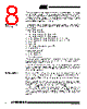
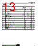
9 / 33 page  9 AT45DB081B 2225I–DFLSH–9/05 WRITE PROTECT: If the WP pin is held low, the first 256 pages of the main memory cannot be reprogrammed. The only way to reprogram the first 256 pages is to first drive the protect pin high and then use the program commands previously mentioned. If this pin and feature are not utilized it is recommended that the WP pin be driven high externally. RESET: A low state on the reset pin (RESET) will terminate the operation in progress and reset the internal state machine to an idle state. The device will remain in the reset condition as long as a low level is present on the RESET pin. Normal operation can resume once the RESET pin is brought back to a high level. The device incorporates an internal power-on reset circuit, so there are no restrictions on the RESET pin during power-on sequences. If this pin and feature are not utilized it is recommended that the RESET pin be driven high externally. READY/BUSY: This open drain output pin will be driven low when the device is busy in an internally self-timed operation. This pin, which is normally in a high state (through a1k Ω external pull-up resistor), will be pulled low during programming operations, com- pare operations, and during page-to-buffer transfers. The busy status indicates that the Flash memory array and one of the buffers cannot be accessed; read and write operations to the other buffer can still be performed. Power-on/Reset State When power is first applied to the device, or when recovering from a reset condition, the device will default to SPI Mode 3. In addition, the SO pin will be in a high-impedance state, and a high-to-low transition on the CS pin will be required to start a valid instruc- tion. The SPI mode will be automatically selected on every falling edge of CS by sampling the inactive clock state. After power is applied and V CC is at the minimum datasheet value, the system should wait 20 ms before an operational mode is started. |
|
链接网址 |
| ALLDATASHEET是否为您带来帮助? [ DONATE ] |
关于 Alldatasheet | 广告服务 | 联系我们 | 隐私政策 | 数据表链接 | 链接交换 | 制造商名单 All Rights Reserved©Alldatasheet.com |
| Russian : Alldatasheetru.com | Korean : Alldatasheet.co.kr | Spanish : Alldatasheet.es | French : Alldatasheet.fr | Italian : Alldatasheetit.com Portuguese : Alldatasheetpt.com | Polish : Alldatasheet.pl | Vietnamese : Alldatasheet.vn Indian : Alldatasheet.in | Mexican : Alldatasheet.com.mx | British : Alldatasheet.co.uk | New Zealand : Alldatasheet.co.nz |
|
Family Site : ic2ic.com |
icmetro.com |
 Chinese ▼
 English
 Chinese
 German
 Japanese
 Russian
 Korean
 Spanish
 French
 Italian
 Portuguese
 Polish
 Vietnamese
 Indian
 Mexican
 British
 New Zealand