|
数据搜索系统,热门电子元器件搜索 |
|
|
数据搜索系统,热门电子元器件搜索 |
|
DMS-EB-RMS-C 数据表(PDF) 2 Page - Murata Power Solutions Inc. |
|
|
|||||||||||||||||||||||||||||
DMS-EB-RMS-C 数据表(HTML) 2 Page - Murata Power Solutions Inc. |
|
|
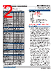
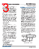
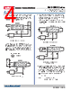
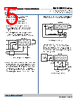
2 / 6 page  Performance/Functional Specifications Typical at TA = +25°C and supply voltage = +5V using the single-ended input circuit, unless otherwise noted. ➀ Applies for transient or continuous overvoltages applied to (+) INPUT HI (pin 11) with (–) INPUT LO (pin 12) properly connected. Pin 12 is not overvoltage protected (see Figure 1). Voltages applied to pin 12 should not exceed the supply voltage. ➁ See Technical Notes. Analog Inputs Min. Typ. Max. Units Full Scale Input Range: DMS-30DR-0 – ±200 – mV DMS-30DR-1 – ±2 – Volts DMS-30DR-2 – ±20 – Volts DMS-30DR-3 – ±200 – Volts Input Impedance: – DMS-30DR-0, -1 100 1000 – M Ω DMS-30DR-2, -3 0.9 1 – M Ω Overvoltage Protection ➀ – – ±250 Volts Common Mode Voltage Range – – ±2 Volts CMRR (dc to 60Hz) – 86 – dB Control Inputs ➁ Decimal Point Placement (Pins 4-6) Tie to pin 3 to activate Ext. Bright (Pin 2) See Technical Note 1 Performance Sampling Rate 2.5 reading per second Accuracy (3 minute warm-up): DMS-30PC-0 (Vin = +0.19V) – ±1 ±3 Counts DMS-30PC-1 (Vin = +1.9V) – ±1 ±3 Counts DMS-30PC-2 (Vin = +19V) – ±2 ±3 Counts DMS-30PC-3 (Vin = +190V) – ±2 ±3 Counts Zero Reading (Vin = 0 Volts) “–001” “000” “001” Temperature Drift (0 = +60°C) – ±0.2 ±0.4 Cnts/°C +1.225V Reference Output (Pin 9) ➁ +1.215 +1.225 +1.235 Volts Power Supply Requirements Supply Voltage +4.75 +5.00 +5.25 Volts Supply Current: Full Sunlight – +150 +250 mA Total Darkness –3 5 mA Display Display Type and Size 3½ digit, 0.56"/14.2mm high LED Polarity Indication Autopolarity ("–" for negative Vin) Overrange Indication "–1_ _ _ " for negative inputs "1_ _ _ " for positive inputs Physical/Environmental Operating Temperature 0 – +60 °C Storage Temperature –40 – +75 °C Humidity (non-condensing) 0 – 95 % Case Material Polycarbonate Weight 0.75 ounces (21 grams) Ordering Informatio n DMS-30DR- 1 - R - C LED Color: R = Red Accessories: DMS-EB-C Multi-purpose (gain/offset, 4-20mA, etc.) DMS-EB-RMS-C For true rms measurements of ac voltages DMS-30-CP Panel cutout punch Input Range: 0 = ±200mV 1 = ±2V 2 = ±20V 3 = ±200V RoHS www.murata-ps.com/support DMS-30DR Series Sunlight Readable, 3½ Digit Panel Meters with Auto-Dimming LED Displays MPM_DMS-30DR.C0 3 Page 2 of 6 A panel-mount DMS-BZL2-C is supplied with each unit. NOTE: See the table on the top of Page 1 for model-specific availability. TECHNICAL NOTES 1. External Brightness Adjustment (Pin 2): Pin 2 is internally con- nected to the high impedance input of an operational amplifier that amplifies the output of the DMS-30DR’s ambient light sensor (ALS) circuit. The output of this amplifier varies the voltage that drives the DMS-30DR’s LED display. Leave pin 2 open for standard auto-dim- ming operation; in this mode, the ALS circuit will automatically adjust the DMS-30DR’s LED brightness to compensate for changes in ambi- ent lighting. As the ambient light striking the ALS increases, the LED display’s brightness will also increase; a decrease in ambient light will reduce the display’s brightness. The ALS circuit’s output signal can be overdriven by applying an externally generated voltage directly to pin 2. External drivers will see approximately 600Kohms referenced to 5V RETURN. With pin 2 at +0.7Vdc or below, the DMS-30DR’s LED display is off, and total cur- rent drain from a nominal +5V supply is approximately 1mA. The LED display’s brightness will increase from minimum to maximum as the voltage applied to pin 2 is varied from +0.8V up to +2.5V, respectively. To enable continuous maximum display brightness, connect pin 2 directly to pin 1 (+5V SUPPLY); in this configuration the total current drain for the meter will be approximately 200mA. 2. Minimum-Intensity Adjustment Potentiometer: Users can adjust the DMS-30DR’s minimum LED brightness to suit their requirements by adjusting the ¾-turn, rear-mounted intensity adjustment poten- tiometer. Please note, this potentiometer will have minimal impact on display brightness in high ambient light environments. See the Mechanical Specifications section for potentiometer locations. The intensity adjustment potentiometer is factory preset to its mid-point position, producing a typical current drain of 7mA. At it’s minimum and maximum positions, current drain is typically 3mA and 13mA, respectively. As viewed from the rear of the meter, with the model number label facing up, turning the potentiometer clockwise increases the display’s intensity. 3. +1.225V REFERENCE OUTPUT (Pin 9): This pin is the output of the meter’s precision +1.225V internal reference IC. Pin 9 is referenced to ANALOG COMMON (pin 10), which in turn sits approximately +2V above pin 3. Pin 9 should be buffered if it’s used to drive external loads since sourcing more than 15µA of current can affect both the |
|
|
链接网址 |
| ALLDATASHEET是否为您带来帮助? [ DONATE ] |
关于 Alldatasheet | 广告服务 | 联系我们 | 隐私政策 | 数据表链接 | 链接交换 | 制造商名单 All Rights Reserved©Alldatasheet.com |
| Russian : Alldatasheetru.com | Korean : Alldatasheet.co.kr | Spanish : Alldatasheet.es | French : Alldatasheet.fr | Italian : Alldatasheetit.com Portuguese : Alldatasheetpt.com | Polish : Alldatasheet.pl | Vietnamese : Alldatasheet.vn Indian : Alldatasheet.in | Mexican : Alldatasheet.com.mx | British : Alldatasheet.co.uk | New Zealand : Alldatasheet.co.nz |
|
Family Site : ic2ic.com |
icmetro.com |
 Chinese ▼
 English
 Chinese
 German
 Japanese
 Russian
 Korean
 Spanish
 French
 Italian
 Portuguese
 Polish
 Vietnamese
 Indian
 Mexican
 British
 New Zealand