|
数据搜索系统,热门电子元器件搜索 |
|
|
数据搜索系统,热门电子元器件搜索 |
|
DMS-EB-RMS-C 数据表(PDF) 3 Page - Murata Power Solutions Inc. |
|
|
|||||||||||||||||||||||||||||
DMS-EB-RMS-C 数据表(HTML) 3 Page - Murata Power Solutions Inc. |
|
|
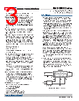
3 / 6 page  1. Single-Ended Input Configurations: True single-ended measure- ments can be made with any DMS-30DR meter. The circuit of Figure 2 avoids problems normally associated with ground-loop currents. Separate ground runs should be used for 5V RETURN (pin 3) and (–) INPUT LO (pin 12). This will ensure that large LED currents will not flow in the wiring that connects VIN to (–) INPUT LO (pin 12). Ground- loop currents can cause unstable readings. Figure 2. Single-Ended Input Configuration DMS-30DR meters are highly versatile devices that can be used in hundreds of applications. The application circuits chosen for this sec- tion have historically received many inquiries. Every attempt has been made to ensure technical accuracy, and all of the following circuits have been prototyped and tested to ensure functionality. Please keep in mind, however, that real-world applications are seldom as straight- forward as the approaches presented here. Most applications have many more components — and many more connections — than the illustrations show. The simplified schematic shown in Figure 1 can be very useful when debugging a malfunctioning panel meter circuit, particularly if the user has some knowledge of operational amplifiers (op amps). The meter's high-impedance input consists of an op amp powered from a ±5Vdc power supply (the –5V is internally generated). Knowing this, one can easily see why input signals applied to (–) INPUT LO and (+) INPUT HI have to be kept within the power supply rails of ±5V. Also note that only pin 11 has a current-limiting 909k Ω series resistor. High input voltages that have a common ground with pin 3 (5V RETURN) should only be applied to pin 11 ((+) INPUT HI) and never to pin 12. In these high-volt- age cases, pin 12 should always be tied to pin 3 (5V RETURN). One of the simplified schematic's noteworthy features is that it shows internal voltage values. It also shows that pin 3 is the meter's zero-volt reference point — regardless of the type of power or signal source used. This is an important point to keep in mind when a digital or analog multimeter is used to make system measurements. The multimeter's negative lead (usually the black one) must be connected to pin 3 (5V RETURN). 1 12 3 +5V SUP (–) IN LO 5V RET 11 (+) IN HI 6 DP1 + – AC to DC Converter VIN DMS-30DR-1 8 7 REF OUT REF IN 85-264Vac www.murata-ps.com/support DMS-30DR Series Sunlight Readable, 3½ Digit Panel Meters with Auto-Dimming LED Displays MPM_DMS-30DR.C0 3 Page 3 of 6 APPLICATIONS accuracy and temperature drift of the meter. A ±1% 1.82K limiting resistor is connected between the reference IC and pin 9. 4. ANALOG COMMON (Pin 10): This pin is connected to an internal, low-noise, “relative” ground. Pin 10 also serves as the internal ground for the +1.225V reference IC. ANALOG COMMON is used in certain differential and “floating” measurements as described in the Applications section of this data sheet, and in DMS Applica- tion Note 3. For the vast majority of applications, pin 10 should not be connected to pin 3 (5V RETURN), or to your system’s analog ground. 5. REFERENCE OUTPUT (Pin 8) and INPUT (Pin 7): Pin 8 is a preci- sion reference actively trimmed at the factory. For normal operation, pin 8 must be tied to pin 7 to achieve all listed accuracy and drift specifications. 6. Decimal Point Placement: The location of the decimal point is user selectable, and the decimal point control pins (DP1-DP3) are active low functions. Select the desired decimal point by tying the appro- priate pin (pin 4, 5 or 6) to pin 3 (5V RETURN). Unused decimal point location pins should be left open. Hard wiring is preferable, however, you can use logic gates to exercise dynamic control over the location of the decimal point if the following drive conditions are met: Applied “0” Voltage: +0.4V max Drive Current*: 6mA max. * The driving gates must be able to sink this much current (IOL) with a logic “0” output. 7. Gain-Adjust Potentiometer: The gain-adjust potentiometer located on the rear of the meter has approximately ±50 counts (±2.5%) of adjustment range with a near full-scale input. Since these meters essentially have no zero/offset errors, a gain adjustment is effectively an overall accuracy adjustment. Though they may be performed at any input level except zero, accuracy adjustments are most effective when performed with half-scale (or higher) positive input signals. If a wider adjustment range is required, an external potentiometer circuit can be configured using the meter’s +1.225V reference output (pin 9). The circuit shown in Figure 9 provides ±10% range of adjustment. 8. Soldering Methods: All models in the DMS-30DR Series easily withstand most common leaded or lead-free soldering opera- tions, performed either manually or by wave soldering machines. However, users should evaluate the effects their particular soldering techniques may have on the meter’s plastic case and precision electrical performance. We highly recommend using low residue, no-clean solders. 9. Suggested Mating Connectors: Panel mounted: Connector housing P/N 4320-01069-0 Terminal type: P/N 4400-01032-0 Crimping tool: P/N 39-2099000 Wire size: 22 to 26 AWG Insulation diameter: 0.062” (1.57mm) maximum Stripping length: 0.100 to 0.125” (2.54 to 3.17mm) Board mounted: Socket: P/N 4320-01074-0 |
|
|
链接网址 |
| ALLDATASHEET是否为您带来帮助? [ DONATE ] |
关于 Alldatasheet | 广告服务 | 联系我们 | 隐私政策 | 数据表链接 | 链接交换 | 制造商名单 All Rights Reserved©Alldatasheet.com |
| Russian : Alldatasheetru.com | Korean : Alldatasheet.co.kr | Spanish : Alldatasheet.es | French : Alldatasheet.fr | Italian : Alldatasheetit.com Portuguese : Alldatasheetpt.com | Polish : Alldatasheet.pl | Vietnamese : Alldatasheet.vn Indian : Alldatasheet.in | Mexican : Alldatasheet.com.mx | British : Alldatasheet.co.uk | New Zealand : Alldatasheet.co.nz |
|
Family Site : ic2ic.com |
icmetro.com |
 Chinese ▼
 English
 Chinese
 German
 Japanese
 Russian
 Korean
 Spanish
 French
 Italian
 Portuguese
 Polish
 Vietnamese
 Indian
 Mexican
 British
 New Zealand