|
数据搜索系统,热门电子元器件搜索 |
|
|
数据搜索系统,热门电子元器件搜索 |
|
PPC405GPR-3JB333Z 数据表(PDF) 51 Page - Applied Micro Circuits Corporation |
|
|
|||||||||||||||||||||||||||||
PPC405GPR-3JB333Z 数据表(HTML) 51 Page - Applied Micro Circuits Corporation |
|
|
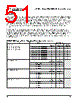
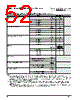
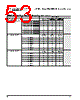
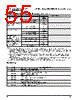
51 / 57 page  405GPr – Power PC 405GPr Embedded Processor AMCC 51 Revision 2.04 – September 7, 2007 Data Sheet Strapping When the SysReset input is driven low by an external device (system reset), the state of certain I/O pins is read to enable default initial conditions prior to PPC405GPr start-up. The actual capture instant is the nearest SysClk edge before the deassertion of reset. These pins must be strapped using external pull-up (logical 1) or pull-down (logical 0) resistors to select the desired default conditions. The recommended pull-up is 3k Ω to +3.3V or 10kΩ to +5V. The recommended pull-down is 1K Ω to GND. These pins are use for strap functions only during reset. They are used for other signals during normal operation. The following tables list the strapping pins along with their functions and strapping options. The signal names assigned to the pins for normal operation follow the pin number. The PPC405GPr can be used as a replacement for the PPC405GP. When the PPC405GPr is used for this purpose, it should be strapped to operate in the PPC405GPr Legacy Mode. This option is selected by strapping ball D20 (GPIO24) low (0). If Legacy Mode is selected, the “PPC405GPr Legacy Mode Strapping Pin Assignments” table should be used to determine the strapping options. To operate the chip as a PPC405GPr, strap D20 (GPIO24) high (1) and use “PPC405GPr New Mode Strapping Pin Assignments” on page 53 to determine the strapping options. PPC405GPr Legacy Mode Strapping Pin Assignments (Sheet 1 of 2) Function Option Ball Strapping PLL Tuning 1 for 6 ≤ M ≤ 7 use choice 3 for 7 < M ≤ 12 use choice 5 for 12 < M ≤ 32 use choice 6 AF3 UART0_Tx AF2 UART0_DTR AD16 UART0_RTS Choice 1; TUNE[9:0] = 1010111100 0 0 0 Choice 2; TUNE[9:0] = 0100111000 0 0 1 Choice 3; TUNE[9:0] = 0100110110 0 1 0 Choice 4; TUNE[9:0] = 0100111100 0 1 1 Choice 5; TUNE[9:0] = 0100111000 1 0 0 Choice 6; TUNE[9:0] = 1000111100 1 0 1 Choice 7; TUNE[9:0] = 1000111110 1 1 0 Choice 8; TUNE[9:0] = 1011111110 1 1 1 PLL Forward Divider 2 D16 DMAAck0 B15 DMAAck1 Bypass mode 0 0 Divide by 3 0 1 Divide by 4 1 0 Divide by 6 1 1 PLL Feedback Divider 2 B14 DMAAck2 C12 DMAAck3 Divide by 1 0 0 Divide by 2 0 1 Divide by 3 1 0 Divide by 4 1 1 PLB Divider from CPU 2 P25 EMCTxD3 L24 EMCTxD2 Divide by 1 0 0 Divide by 2 0 1 Divide by 3 1 0 Divide by 4 1 1 |
|
链接网址 |
| ALLDATASHEET是否为您带来帮助? [ DONATE ] |
关于 Alldatasheet | 广告服务 | 联系我们 | 隐私政策 | 数据表链接 | 链接交换 | 制造商名单 All Rights Reserved©Alldatasheet.com |
| Russian : Alldatasheetru.com | Korean : Alldatasheet.co.kr | Spanish : Alldatasheet.es | French : Alldatasheet.fr | Italian : Alldatasheetit.com Portuguese : Alldatasheetpt.com | Polish : Alldatasheet.pl | Vietnamese : Alldatasheet.vn Indian : Alldatasheet.in | Mexican : Alldatasheet.com.mx | British : Alldatasheet.co.uk | New Zealand : Alldatasheet.co.nz |
|
Family Site : ic2ic.com |
icmetro.com |
 Chinese ▼
 English
 Chinese
 German
 Japanese
 Russian
 Korean
 Spanish
 French
 Italian
 Portuguese
 Polish
 Vietnamese
 Indian
 Mexican
 British
 New Zealand