|
数据搜索系统,热门电子元器件搜索 |
|
|
数据搜索系统,热门电子元器件搜索 |
|
PPC405GPR-3JB333Z 数据表(PDF) 55 Page - Applied Micro Circuits Corporation |
|
|
|||||||||||||||||||||||||||||
PPC405GPR-3JB333Z 数据表(HTML) 55 Page - Applied Micro Circuits Corporation |
|
|
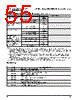
55 / 57 page  405GPr – Power PC 405GPr Embedded Processor AMCC 55 Revision 2.04 – September 7, 2007 Data Sheet Revision Log PCI Asynchronous Mode Enable Y3 ExtAck Synchronous PCI Mode 0 Asynchronous Mode 1 External Bus Synchronous Mode Enable 3 A22 GPIO3[TS1O] Asynchronous Mode 0 Synchronous Mode 1 PCI Arbiter Enable 3 AF18 GPIO4[TS2O] Internal Arbiter Disabled 0 Internal Arbiter Enabled 1 New Mode Enable In Legacy mode the PPC405GPr functions like the PPC405GP. If not strapped, the PPC405GPr defaults to Legacy mode. D20 GPIO24 Legacy (PPC405GP) mode 0 New (PPC405GPr) mode4 1 Flip Circuit Disable (must be strapped low (0) during initilization). AB3 GPIO9[TrcClk] Normal operation 0 Note: 1. The tune bits adjust parameters that control PLL jitter. The recommended values minimize jitter for the PLL implemented in the PPC405GPr. These bits are shown for information only; and do not require modification except in special clocking circumstances such as spread spectrum clocking. For details on the use of Spread Spectrum Clock Generators (SSCGs) with the PPC405GPr, visit the technical documents area of the AMCC PowerPC web site. 2. Not all combinations of dividers produce valid operating configurations. Frequencies must be within the limits specified in “Clocking Specifications” on page 43. Further requirements are detailed in the Clocking chapter of the PowerPC 405GPr Embedded Processor User’s Manual. 3. Additional consideration must be given to pins that normally function as Trace signals. Improved design margin can be gained by using three-state buffers instead of strapping resistors, and minimizing trace lengths and stubs. 4. The pull-up initialization strapping resistor must be 1k Ω rather than 3kΩ in order to overcome the internal pull-down resistor. Date Contents of Modification 03/13/2003 400MHz part numbers and new power/current numbers 08/28/2003 Add new VDD values for 400MHz parts. 11/22/2004 Correct package drawings and add lead-free part numbers. Add +105 °C temperature specification. Add 1 ms. voltage ramp-up restriction. 12/02/2004 Update to AMCC format. 01/06/2005 Correct typographical error in 27mm package drawing. 08/29/2005 Add dashes back into PNs. 03/13/2007 Revise package drawings to add logo view. Update AMCC address and copyright date on last page. 09/07/2007 Change TestEn signal from active low to active high. Correct AMCC telephone numbers. PPC405GPr New Mode Strapping Pin Assignments (Sheet 3 of 3) Function Option Ball Strapping |
|
链接网址 |
| ALLDATASHEET是否为您带来帮助? [ DONATE ] |
关于 Alldatasheet | 广告服务 | 联系我们 | 隐私政策 | 数据表链接 | 链接交换 | 制造商名单 All Rights Reserved©Alldatasheet.com |
| Russian : Alldatasheetru.com | Korean : Alldatasheet.co.kr | Spanish : Alldatasheet.es | French : Alldatasheet.fr | Italian : Alldatasheetit.com Portuguese : Alldatasheetpt.com | Polish : Alldatasheet.pl | Vietnamese : Alldatasheet.vn Indian : Alldatasheet.in | Mexican : Alldatasheet.com.mx | British : Alldatasheet.co.uk | New Zealand : Alldatasheet.co.nz |
|
Family Site : ic2ic.com |
icmetro.com |
 Chinese ▼
 English
 Chinese
 German
 Japanese
 Russian
 Korean
 Spanish
 French
 Italian
 Portuguese
 Polish
 Vietnamese
 Indian
 Mexican
 British
 New Zealand