|
数据搜索系统,热门电子元器件搜索 |
|
|
数据搜索系统,热门电子元器件搜索 |
|
K3HB-R 数据表(PDF) 12 Page - Omron Electronics LLC |
|
|
|||||||||||||||||||||||||||||
K3HB-R 数据表(HTML) 12 Page - Omron Electronics LLC |
|
|
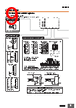
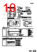
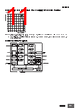
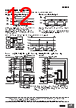
12 / 17 page  K3HB-R 12 ■ BCD Output Timing Chart A REQUEST signal from a Programmable Controller or other external device is required to read BCD data. Single Sampling Data Output The data is set in approximately 30 ms from the rising edge of the REQUEST signal and the DATA VALID signal is output. When reading the data from a Programmable Controller, start reading the data when the DATA VALID signal turns ON. The DATA VALID signal will turn OFF 40 ms later, and the data will turn OFF 16 ms after that. Continuous Data Output Measurement data is output every 64 ms while the REQUEST signal remains ON. Note: If HOLD is executed when switching between data 1 and data 2, either data 1 or data 2 is output depending on the timing of the hold signal. The data will not go LOW. Approx. 30 ms All data "High" All data "High" 40 ms 16 ms Data REQ. MAX.MIN. DATA DATA VALID 20-ms pulse min. (50 ms max.) Approx. 30 ms Data 1 Data 2 REQ. MAX.MIN. DATA DATA VALID 64 ms 64 ms 40 ms 40 ms 24 ms 24 ms All data "High" K3HB (1) Programmable Controller K3HB (2) K3HB (3) DATA (including POL and OVER) and DATA VALID can be used in a wired OR. RUN, HH, H, PASS, L, and LL are always output, with or without a REQUEST signal. Do not used a wired OR connect for these signals. DATA REQ. (1) (1) (2) (3) REQ. (2) REQ. (3) DATA VALID Note: Leave 20 ms min. between DATA VALID turning OFF and the REQUEST signal. (See note.) (See note.) (See note.) • The K3HB BCD output model has an open collector output, so wired OR connection is possible Programmable Controller Connection Example Digital Indicator SYSMAC Programmable Controller DC Input Unit 1.COMMON Connector pin No. (See note.) COM IN IN IN IN IN IN OUT OUT COM 24 VDC (0 V) 2.1 3.2 4.4 5.8 23.DATA VALID 24.RUN 25.COMMON 26.REQUEST 30.RESET 31.POLARITY ( +/− polarity) 10 ° 240 Ω 240 Ω 240 Ω 240 Ω +5 V +24 V 0 V DC power supply Transistor Output Unit Display Unit Connection Example To 102 <M7E Digital Display Unit> SEC Digital Indicator 1.COMMON Connector pin No. (See note.) 2.1 3.2 4.4 5.8 23.DATA VALID 24.RUN 25.COMMON 26.REQUEST 30.RESET M7E-01D @N2, 01H@N2 31.POLARITY ( +/− polarity) 10 ° To 101 240 Ω 240 Ω 240 Ω 240 Ω +5 V 8 8 8 Short- circuit Note: The BCD output connector pin number is the D-sub connector pin number when the BCD Output Cable (sold separately) is connected. This number differs from the pin number for the Digital Indicator narrow pitch connector (manufactured by Honda Tsushin Kogyo Co., Ltd.). Refer to the following User's Manual for application precautions and other information required when using the Digital Indicator: K3HB-R/P/C Digital Indicator User's Manual (Cat. No. N136) The manual can be downloaded from the following site in PDF format: OMRON Industrial Web http://www.fa.omron.co.jp |
|
|
链接网址 |
| ALLDATASHEET是否为您带来帮助? [ DONATE ] |
关于 Alldatasheet | 广告服务 | 联系我们 | 隐私政策 | 数据表链接 | 链接交换 | 制造商名单 All Rights Reserved©Alldatasheet.com |
| Russian : Alldatasheetru.com | Korean : Alldatasheet.co.kr | Spanish : Alldatasheet.es | French : Alldatasheet.fr | Italian : Alldatasheetit.com Portuguese : Alldatasheetpt.com | Polish : Alldatasheet.pl | Vietnamese : Alldatasheet.vn Indian : Alldatasheet.in | Mexican : Alldatasheet.com.mx | British : Alldatasheet.co.uk | New Zealand : Alldatasheet.co.nz |
|
Family Site : ic2ic.com |
icmetro.com |
 Chinese ▼
 English
 Chinese
 German
 Japanese
 Russian
 Korean
 Spanish
 French
 Italian
 Portuguese
 Polish
 Vietnamese
 Indian
 Mexican
 British
 New Zealand