30 / 111 page 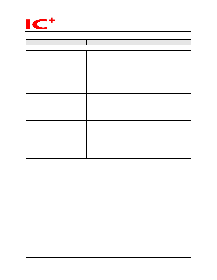 IP175C/IP175C LF/IP175CH/IP175CH LF Data Sheet 30/111 Mar 09, 2007 Copyright © 2004, IC Plus Corp. IP175C/IP175CH-DS-R14 Pin description (continued) Pin No. Label Type Description Transceiver 127, 128, 11, 12, 18, 19, 29, 30, 33, 34 RXIP0, RXIM0, RXIP1, RXIM1, RXIP2, RXIM2, RXIP3, RXIM3, RXIP4, RXIM4 I TP receive 3, 4, 8, 9, 21, 22, 26, 27, 37, 38 TXOP0, TXOM0, TXOP1, TXOM1, TXOP2, TXOM2, TXOP3, TXOM3, TXOP4, TXOM4 O TP transmit 15 BGRES O Band gap resister. It is connected to GND through a 6.19 k ohm resistor. Please refer to application circuit for more information. 125, 41, 42, 43, 44 NC I 44 FXSD4 (IP175CH only) I 100Base-FX Signal detect Port 4 of IP175C can be configured to TP or FX. If FXSD4 is connected to SD of a fiber MAU, port 4 is a fiber port. If FXSD4 is tied to GND, the port 4 is a TP port. If port 4 is defined to be a fiber port, its speed is forced to be 100M and its duplex is defined in its MII register 4.0.8. Please refer section 2.19 on page 56 for more detail description. |
|

 Chinese ▼
 English
 Chinese
 German
 Japanese
 Russian
 Korean
 Spanish
 French
 Italian
 Portuguese
 Polish
 Vietnamese
 Indian
 Mexican
 British
 New Zealand