|
数据搜索系统,热门电子元器件搜索 |
|
|
数据搜索系统,热门电子元器件搜索 |
|
GS-R1012 数据表(PDF) 5 Page - STMicroelectronics |
|
|
|||||||||||||||||||||||||||||
GS-R1012 数据表(HTML) 5 Page - STMicroelectronics |
|
|
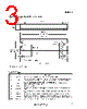
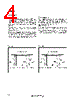
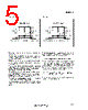
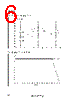
5 / 7 page  5/7 Thermal characterist ics: how to choose the heat-sink Sometimes the GS-R1012 requires an external heat-sink depending both operating temperature conditions and power. Before entering into calculations details, some ba- sic concepts will be explained to better understand the problem. The thermal resistance between two points is rep- resented by their temperature difference in front of a specified dissipated power, and it is expressed in Degree Centigrade per Watt ( °C/W). For GS-R1012 the thermal resistance case to am- bient is 7.5 °C/W. This means that an internal power dissipation of 1W will bring the case temperature at 7.5 °C above the ambient temperature. The maximum case temperature to which the mod- ule provides 10A is 75 °C (see fig. 6). Let’s suppose to have a GS-R1012 that delivers a load current of 10A at an ambient temperature of 40 °C. The dissipated power in this operating condition is about 10.4W (at typical efficiency of 92%), and the case temperature of the module will be: TCase = TAmb + Pd × Rth = 40 + 10.4 × 7.5 = 118°C This value exceeds the maximum allowed tempera- ture and an external heat-sink must be added. To this purpose four holes (see mechanical drawing) are provided on the metal surface of the module. To calculate this heat-sink, let’s first determine what the total thermal resistance should be. Rth = TCaseMAX − Tamb Pd = 75 − 40 10.4 = 3.37°C/ W This value is the resulting value of the additional heatsink thermal resistance. Figure 3. Figure 4. GS-R1012 |
|
|
链接网址 |
| ALLDATASHEET是否为您带来帮助? [ DONATE ] |
关于 Alldatasheet | 广告服务 | 联系我们 | 隐私政策 | 数据表链接 | 链接交换 | 制造商名单 All Rights Reserved©Alldatasheet.com |
| Russian : Alldatasheetru.com | Korean : Alldatasheet.co.kr | Spanish : Alldatasheet.es | French : Alldatasheet.fr | Italian : Alldatasheetit.com Portuguese : Alldatasheetpt.com | Polish : Alldatasheet.pl | Vietnamese : Alldatasheet.vn Indian : Alldatasheet.in | Mexican : Alldatasheet.com.mx | British : Alldatasheet.co.uk | New Zealand : Alldatasheet.co.nz |
|
Family Site : ic2ic.com |
icmetro.com |
 Chinese ▼
 English
 Chinese
 German
 Japanese
 Russian
 Korean
 Spanish
 French
 Italian
 Portuguese
 Polish
 Vietnamese
 Indian
 Mexican
 British
 New Zealand