|
数据搜索系统,热门电子元器件搜索 |
|
|
数据搜索系统,热门电子元器件搜索 |
|
SSM2301RMZ-R2 数据表(PDF) 12 Page - Analog Devices |
|
|
|||||||||||||||||||||||||||||
SSM2301RMZ-R2 数据表(HTML) 12 Page - Analog Devices |
|
|
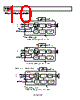
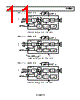
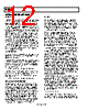
12 / 16 page  SSM2301 Rev. A | Page 12 of 16 APPLICATIONS INFORMATION OVERVIEW The SSM2301 mono Class-D audio amplifier features a filterless modulation scheme that greatly reduces external component count, conserving board space and, thus, reducing system cost. The SSM2301 does not require an output filter but, instead, relies on the inherent inductance of the speaker coil and the natural filtering of the speaker and human ear to fully recover the audio component of the square-wave output. While most Class-D ampli- fiers use some variation of pulse-width modulation (PWM), the SSM2301 uses a Σ-Δ modulation to determine the switching pattern of the output devices. This provides a number of important benefits. Σ-Δ modulators do not produce a sharp peak with many harmonics in the AM frequency band, as pulse-width modulators often do. Σ-Δ modulation reduces the amplitude of spectral components at high frequencies, thereby reducing EMI emission that might otherwise be radiated by speakers and long cable traces. The SSM2301 also offers protection circuitry for output short- circuit and high temperature conditions. When the fault-inducing condition is removed, the SSM2301 automatically recovers without the need for a hard reset. GAIN SELECTION Pulling the GAIN pin of the SSM2301 high sets the gain of the speaker amplifier to 12 dB; pulling it low sets the gain of the speaker amplifier to 6 dB. It is possible to adjust the SSM2301 gain by using external resistors at the input. To set a gain lower than 12 dB, see Figure 26 for differential input configuration and Figure 27 for single-ended configuration. For external gain configuration from a fixed 12 dB gain, use the following formula: External Gain Settings = 20 log[4/(1 + R/150 kΩ)] To set a gain lower than 6 dB, see Figure 28 for differential input configuration and Figure 29 for single-ended configuration. For external gain configuration from a fixed 6 dB gain, use the following formula: External Gain Settings = 20 log[2/(1 + R/150 kΩ)] POP-AND-CLICK SUPPRESSION Voltage transients at the output of audio amplifiers may occur when shutdown is activated or deactivated. Voltage transients as low as 10 mV can be heard as an audio pop in the speaker. Clicks and pops can also be classified as undesirable audible transients generated by the amplifier system and, therefore, as not coming from the system input signal. Such transients may be generated when the amplifier system changes its operating mode. For example, the following can be sources of audible transients: system power-up/power-down, mute/unmute, input source change, and sample rate change. The SSM2301 has a pop- and-click suppression architecture that reduces these output transients, resulting in noiseless activation and deactivation. LAYOUT As output power continues to increase, care must be taken to lay out PCB traces and wires properly between the amplifier, load, and power supply. A good practice is to use short, wide PCB tracks to decrease voltage drops and minimize inductance. Make track widths at least 200 mil for every inch of track length for lowest DCR, and use 1 oz or 2 oz of copper PCB traces to further reduce IR drops and inductance. Poor layout increases voltage drops, consequently affecting efficiency. Use large traces for the power supply inputs and amplifier outputs to minimize losses due to parasitic trace resistance. Proper grounding guidelines help improve audio performance, minimize crosstalk between channels, and prevent switching noise from coupling into the audio signal. To maintain high output swing and high peak output power, PCB traces that connect the output pins to the load and supply pins should be as wide as possible to maintain the minimum trace resistances. It is also recommended that a large-area ground plane be used for minimum impedances. Good PCB layouts also isolate critical analog paths from sources of high interference. High frequency circuits (analog and digital) should be separated from low frequency circuits. Properly designed multilayer printed circuit boards can reduce EMI emission and increase immunity to the RF field by a factor of 10 or more compared with double-sided boards. A multilayer board allows a complete layer to be used for the ground plane, whereas the ground plane side of a double- side board is often disrupted with signal crossover. If the system has separate analog and digital ground and power planes, the analog ground plane should be underneath the analog power plane, and, similarly, the digital ground plane should be underneath the digital power plane. There should be no overlap between analog and digital ground planes or analog and digital power planes. INPUT CAPACITOR SELECTION The SSM2301 does not require input coupling capacitors if the input signal is biased from 1.0 V to VDD − 1.0 V. Input capacitors are required if the input signal is not biased within this recom- mended input dc common-mode voltage range, if high-pass filtering is needed (see Figure 24) or if using a single-ended source (see Figure 25). If high-pass filtering is needed at the input, the input capacitor, along with the input resistor of the SSM2301, forms a high-pass filter whose corner frequency is determined by the following equation: fC = 1/(2π × RIN × CIN) The input capacitor can have very important effects on the circuit performance. Not using input capacitors degrades the output offset of the amplifier as well as the PSRR performance. |
|
|
链接网址 |
| ALLDATASHEET是否为您带来帮助? [ DONATE ] |
关于 Alldatasheet | 广告服务 | 联系我们 | 隐私政策 | 数据表链接 | 链接交换 | 制造商名单 All Rights Reserved©Alldatasheet.com |
| Russian : Alldatasheetru.com | Korean : Alldatasheet.co.kr | Spanish : Alldatasheet.es | French : Alldatasheet.fr | Italian : Alldatasheetit.com Portuguese : Alldatasheetpt.com | Polish : Alldatasheet.pl | Vietnamese : Alldatasheet.vn Indian : Alldatasheet.in | Mexican : Alldatasheet.com.mx | British : Alldatasheet.co.uk | New Zealand : Alldatasheet.co.nz |
|
Family Site : ic2ic.com |
icmetro.com |
 Chinese ▼
 English
 Chinese
 German
 Japanese
 Russian
 Korean
 Spanish
 French
 Italian
 Portuguese
 Polish
 Vietnamese
 Indian
 Mexican
 British
 New Zealand