|
数据搜索系统,热门电子元器件搜索 |
|
|
数据搜索系统,热门电子元器件搜索 |
|
SSM2250RMZ-R21 数据表(PDF) 9 Page - Analog Devices |
|
|
|||||||||||||||||||||||||||||
SSM2250RMZ-R21 数据表(HTML) 9 Page - Analog Devices |
|
|
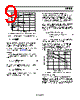
9 / 12 page  SSM2250 Rev. A | Page 9 of 12 OUTPUT POWER (W) 0.35 0.3 0.25 0.2 0.15 0.1 0.05 0 0 0.3 0.2 0.1 0.4 VDD = 5V RL = 16Ω RL = 8Ω RL = 4Ω Figure 16. Power Dissipation vs. Single-Ended Output Power (VDD = 5 V) The maximum power dissipation for a single-ended output is L DD MAX DISS R V P 2 2 , 2π = (5) Because the SSM2250 is designed to drive two single-ended loads simultaneously, the worst-case maximum power dissipation in SE mode is twice the value of Equation 5. A thorough mathematical explanation behind Equation 4 and Equation 5 is provided in the SSM2211 data sheet. Example Given worst-case stereo headphone loads of 32 Ω, the maxi- mum power dissipation of the SSM2250 in SE mode with a 5 V supply is () mW V P MAX DISS 79 32 2 5 2 2 , = Ω π = (6) With an 8 Ω internal speaker attached, the maximum power dissipation in BTL mode is (from Equation 4) () mW V P MAX DISS 633 8 5 2 2 2 , = Ω π × = (7) It can easily be seen that power dissipation from BTL mode operation is of greater concern than SE mode. Solving for Maximum Ambient Temperature To protect the SSM2250 against thermal damage, the junction temperature of the die should not exceed 150°C. The maximum allowable ambient temperature of the application can be easily found by solving for the expected maximum power dissipation in Equation 4 and Equation 5, and using Equation 8. Continuing from the previous example, the θJA of the SSM2250 14-lead TSSOP package on a 4-layer board is 140°C/W. To ensure that the SSM2250 die junction temperature stays below 150°C, the maximum ambient temperature can be solved using Equation 8. ( C W W C C P C T MAX DISS JA MAX AMB o o o o 61 633 . 0 / 140 150 150 , , + = × − + = × θ − + = ) (8) The maximum ambient temperature must remain below 61°C to protect the device against thermal damage. Another method for finding the maximum allowable ambient temperature is to use the power derating curve in Figure 17. The y-axis corresponds to the expected maximum power dissipation, and the x-axis is the corresponding maximum ambient temperature. Either method returns the same answer. AMBIENT TEMPERATURE (°C) 1.0 0.8 0.6 0.4 0.2 0 07 50 25 100 5 14-LEAD TSSOP θ JA = 140°C/W 10-LEAD MSOP θ JA = 180°C/W TJMAX = 150°C/W FREE AIR NO HEAT SINK Figure 17. Maximum Power Dissipation vs. Ambient Temperature Maximum Output Power The maximum amount of power that can be delivered to a speaker is a function of the supply voltage and the resistance of the speaker. Figure 17 shows the maximum BTL output power possible from the SSM2250. Maximum output power is defined as the point at which the output has greater than 1% distortion. |
|
|
链接网址 |
| ALLDATASHEET是否为您带来帮助? [ DONATE ] |
关于 Alldatasheet | 广告服务 | 联系我们 | 隐私政策 | 数据表链接 | 链接交换 | 制造商名单 All Rights Reserved©Alldatasheet.com |
| Russian : Alldatasheetru.com | Korean : Alldatasheet.co.kr | Spanish : Alldatasheet.es | French : Alldatasheet.fr | Italian : Alldatasheetit.com Portuguese : Alldatasheetpt.com | Polish : Alldatasheet.pl | Vietnamese : Alldatasheet.vn Indian : Alldatasheet.in | Mexican : Alldatasheet.com.mx | British : Alldatasheet.co.uk | New Zealand : Alldatasheet.co.nz |
|
Family Site : ic2ic.com |
icmetro.com |
 Chinese ▼
 English
 Chinese
 German
 Japanese
 Russian
 Korean
 Spanish
 French
 Italian
 Portuguese
 Polish
 Vietnamese
 Indian
 Mexican
 British
 New Zealand