|
数据搜索系统,热门电子元器件搜索 |
|
|
数据搜索系统,热门电子元器件搜索 |
|
AD8532ARMZ-R2 数据表(PDF) 12 Page - Analog Devices |
|
|
|||||||||||||||||||||||||||||
AD8532ARMZ-R2 数据表(HTML) 12 Page - Analog Devices |
|
|
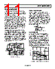
12 / 20 page  AD8531/AD8532/AD8534 Rev. F | Page 12 of 20 The thermal resistance curves were determined using the AD8531/AD8532/AD8534 thermal resistance data for each package and a maximum junction temperature of 150°C. The following formula can be used to calculate the internal junction temperature of the AD8531/AD8532/AD8534 for any application: TJ = PDISS × θJA + TA where: TJ is the junction temperature. PDISS is the power dissipation. θJA is the package thermal resistance, junction-to-case. TA is the ambient temperature of the circuit. To calculate the power dissipated by the AD8531/AD8532/ AD8534, the following equation can be used: PDISS = ILOAD × (VS − VOUT) where: ILOAD is the output load current. VS is the supply voltage. VOUT is the output voltage. The quantity within the parentheses is the maximum voltage developed across either output transistor. As an additional design aid in calculating available load current from the AD8531/AD8532/AD8534, Figure 5 illustrates the output voltage of the AD8531/AD8532/AD8534 as a function of load resistance. POWER CALCULATIONS FOR VARYING OR UNKNOWN LOADS Often, calculating power dissipated by an integrated circuit to determine if the device is being operated in a safe range is not as simple as it may seem. In many cases, power cannot be directly measured, which may be the result of irregular output waveforms or varying loads; indirect methods of measuring power are required. There are two methods to calculate power dissipated by an integrated circuit. The first can be done by measuring the package temperature and the board temperature, and the other is to directly measure the supply current of the circuit. CALCULATING POWER BY MEASURING AMBIENT AND CASE TEMPERATURE Given the two equations for calculating junction temperature TJ = TA + PDISS θJA where: TJ is the junction temperature. TA is the ambient temperature. θJA is the junction to ambient thermal resistance. TJ = TC + PDISS θJA where: TC is the case temperature. θJA and θJC are given in the data sheet. The two equations can be solved for P (power) TA + PDISS θJA = TC + PθJC PDISS = (TA − TC)/(θJC − θJA) Once power is determined, it is necessary to go back and calculate the junction temperature to ensure that it has not been exceeded. The temperature measurements should be directly on the package and on a spot on the board that is near the package but not touching it. Measuring the package could be difficult. A very small bimetallic junction glued to the package can be used, or measurement can be done using an infrared sensing device if the spot size is small enough. CALCULATING POWER BY MEASURING SUPPLY CURRENT Power can be calculated directly, knowing the supply voltage and current. However, supply current may have a dc component with a pulse into a capacitive load, which can make rms current very difficult to calculate. It can be overcome by lifting the supply pin and inserting an rms current meter into the circuit. For this to work, be sure the current is being delivered by the supply pin being measured. This is usually a good method in a single-supply system; however, if the system uses dual supplies, both supplies may need to be monitored. INPUT OVERVOLTAGE PROTECTION As with any semiconductor device, whenever the condition exists for the input to exceed either supply voltage, the input overvoltage characteristic of the device must be considered. When an overvoltage occurs, the amplifier can be damaged, depending on the magnitude of the applied voltage and the magnitude of the fault current. Although not shown here, when the input voltage exceeds either supply by more than 0.6 V, pn junctions internal to the AD8531/AD8532/AD8534 energize, allowing current to flow from the input to the supplies. As illustrated in the simplified equivalent input circuit (see Figure 36), the AD8531/AD8532/AD8534 do not have any internal current limiting resistors; therefore, fault currents can quickly rise to damaging levels. This input current is not inherently damaging to the device, as long as it is limited to 5 mA or less. For the AD8531/AD8532/ AD8534, once the input voltage exceeds the supply by more than 0.6 V, the input current quickly exceeds 5 mA. If this condition continues to exist, an external series resistor should be added. The size of the resistor is calculated by dividing the maximum overvoltage by 5 mA. For example, if the input voltage could reach 10 V, the external resistor should be (10 V/5 mA) = 2 kΩ. This resistance should be placed in series with either or both inputs if they are exposed to an overvoltage condition. |
|
|
链接网址 |
| ALLDATASHEET是否为您带来帮助? [ DONATE ] |
关于 Alldatasheet | 广告服务 | 联系我们 | 隐私政策 | 数据表链接 | 链接交换 | 制造商名单 All Rights Reserved©Alldatasheet.com |
| Russian : Alldatasheetru.com | Korean : Alldatasheet.co.kr | Spanish : Alldatasheet.es | French : Alldatasheet.fr | Italian : Alldatasheetit.com Portuguese : Alldatasheetpt.com | Polish : Alldatasheet.pl | Vietnamese : Alldatasheet.vn Indian : Alldatasheet.in | Mexican : Alldatasheet.com.mx | British : Alldatasheet.co.uk | New Zealand : Alldatasheet.co.nz |
|
Family Site : ic2ic.com |
icmetro.com |
 Chinese ▼
 English
 Chinese
 German
 Japanese
 Russian
 Korean
 Spanish
 French
 Italian
 Portuguese
 Polish
 Vietnamese
 Indian
 Mexican
 British
 New Zealand