|
数据搜索系统,热门电子元器件搜索 |
|
|
数据搜索系统,热门电子元器件搜索 |
|
AM261...ZFG 数据表(PDF) 67 Page - Texas Instruments |
|
|
|||||||||||||||||||||||||||||
AM261...ZFG 数据表(HTML) 67 Page - Texas Instruments |
|
|
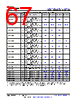
67 / 218 page  Table 5-32. GPMC0 Signal Descriptions (continued) Signal Name [1] Pin Type [2] Description [3] ZCZ PIN [4] ZFG PIN [4] ZEJ PIN [4] ZNC PIN [4] GPMC0_AD7 IO GPMC Data 7 Input/Output in A/D non-multiplexed mode and additionally Address 8 Output in A/D multiplexed mode D11 D15 B13 B14 GPMC0_AD8 IO GPMC Data 8 Input/Output in A/D non-multiplexed mode and additionally Address 9 Output in A/D multiplexed mode B9, E1 B11, F2 D8, E3 B10, E3 GPMC0_AD9 IO GPMC Data 9 Input/Output in A/D non-multiplexed mode and additionally Address 10 Output in A/D multiplexed mode R16 Y17 R15 V16 GPMC0_AD10 IO GPMC Data 10 Input/Output in A/D non-multiplexed mode and additionally Address 11 Output in A/D multiplexed mode D14 C16 A15 GPMC0_AD11 O GPMC Data 11 Input/Output in A/D non-multiplexed mode and additionally Address 12 Output in A/D multiplexed mode N1 R2 M2 N2 GPMC0_AD12 O GPMC Data 12 Input/Output in A/D non-multiplexed mode and additionally Address 13 Output in A/D multiplexed mode N4 R1 N1 N1 GPMC0_AD13 IO GPMC Data 13 Input/Output in A/D non-multiplexed mode and additionally Address 14 Output in A/D multiplexed mode D13 B17 C14 GPMC0_AD14 IO GPMC Data 14 Input/Output in A/D non-multiplexed mode and additionally Address 15 Output in A/D multiplexed mode A15 B18 B15 GPMC0_AD15 IO GPMC Data 15 Input/Output in A/D non-multiplexed mode and additionally Address 16 Output in A/D multiplexed mode H2 H1 E1 F1 GPMC0_BE0n_CLE O GPMC Lower-Byte Enable (active low) or Command Latch Enable C13 A17 A14 A16 GPMC0_BE1n O GPMC Upper-Byte Enable (active low) B11 C12 A11 B11 GPMC0_CSn0 O GPMC Chip Select 0 (active low) A14, B8 B10, B16 B8, C13 A10, A15 GPMC0_CSn1 O GPMC Chip Select 1 (active low) G3 H2 E2 E1 GPMC0_CSn2 O GPMC Chip Select 2 (active low) U18 Y19 R16 W18 GPMC0_CSn3 O GPMC Chip Select 3 (active low) T18 W19 N14 V18 GPMC0_WAIT0 I GPMC External Indication of Wait C9 D11 B9 GPMC0_WAIT1 I GPMC External Indication of Wait C7 C7 C8 C9 (1) The RXACTIVE bit of the MSS_IOMUX:PR0_PRU0_GPO9_CFG_REG register must be set to 0x1 and the TX_DIS bit of the MSS_IOMUX:PR0_PRU0_GPO9_CFG_REG register must be reset to 0x0 when GPMC0 is operating in synchronous mode. (2) GPMC0_CLKLB is a clock loopback signal used internally for retiming purposes. www.ti.com AM2612, AM2611, AM2611-Q1, AM2612-Q1 SPRSPA7C – SEPTEMBER 2024 – REVISED JULY 2025 Copyright © 2025 Texas Instruments Incorporated Submit Document Feedback 67 Product Folder Links: AM2612 AM2611 AM2611-Q1 AM2612-Q1 |
|
链接网址 |
| ALLDATASHEET是否为您带来帮助? [ DONATE ] |
关于 Alldatasheet | 广告服务 | 联系我们 | 隐私政策 | 数据表链接 | 链接交换 | 制造商名单 All Rights Reserved©Alldatasheet.com |
| Russian : Alldatasheetru.com | Korean : Alldatasheet.co.kr | Spanish : Alldatasheet.es | French : Alldatasheet.fr | Italian : Alldatasheetit.com Portuguese : Alldatasheetpt.com | Polish : Alldatasheet.pl | Vietnamese : Alldatasheet.vn Indian : Alldatasheet.in | Mexican : Alldatasheet.com.mx | British : Alldatasheet.co.uk | New Zealand : Alldatasheet.co.nz |
|
Family Site : ic2ic.com |
icmetro.com |
 Chinese ▼
 English
 Chinese
 German
 Japanese
 Russian
 Korean
 Spanish
 French
 Italian
 Portuguese
 Polish
 Vietnamese
 Indian
 Mexican
 British
 New Zealand