|
数据搜索系统,热门电子元器件搜索 |
|
|
数据搜索系统,热门电子元器件搜索 |
|
AD8506ARMZ-R2 数据表(PDF) 15 Page - Analog Devices |
|
|
|||||||||||||||||||||||||||||
AD8506ARMZ-R2 数据表(HTML) 15 Page - Analog Devices |
|
|
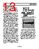
15 / 20 page  AD8506/AD8508 Rev. A | Page 15 of 20 APPLICATIONS INFORMATION PULSE OXIMETER CURRENT SOURCE A pulse oximeter is a noninvasive medical device used for measur- ing continuously the percentage of hemoglobin (Hb) saturated with oxygen and the pulse rate of a patient. Hemoglobin that is carrying oxygen (oxyhemoglobin) absorbs light in the infrared (IR) region of the spectrum; hemoglobin that is not carrying oxygen (deoxyhemoglobin) absorbs visible red (R) light. In pulse oximetry, a clip containing two LEDs (sometimes more, depending on the complexity of the measurement algorithm) and the light sensor (photodiode) is placed on the finger or earlobe of the patient. One LED emits red light (600 nm to 700 nm) and the other emits light in the near IR (800 nm to 900 nm) region. The clip is connected by a cable to a processor unit. The LEDs are rapidly and sequentially excited by two current sources (one for each LED), whose dc levels depend on the LED being driven, based on manufacturer requirements, and the detector is synchro- nized to capture the light from each LED as it is transmitted through the tissue. An example design of a dc current source driving the red and infrared LEDs is shown in Figure 45. These dc current sources allow 62.5 mA and 101 mA to flow through the red and infrared LEDs, respectively. First, to prolong battery life, the LEDs are driven only when needed. One-third of the ADG733 SPDT analog switch is used to disconnect/connect the 1.25 V voltage reference from/to each current circuit. When driving the LEDs, the ADR1581 1.25 V voltage reference is buffered by ½ of the AD8506; the presence of this voltage on the noninverting input forces the output of the op amp (due to the negative feedback) to maintain a level that makes its inverting input-to-track the noninverting pin. Therefore, the 1.25 V appears in parallel with the 20 Ω R1 or 12.4 Ω R5 current source resistor, creating the flow of the 62.5 mA or 101 mA current through the red or infrared LED as the output of the op amp turns on the Q1 or Q2 N-MOSFET IRLMS2002. The maximum total quiescent currents for the ½ AD8506, ADR1581, and ADG733 are 25 μA, 70 μA, and 1 μA, respectively, making a total of 96 μA current consumption (480 μW power consumption) per circuit, which is good for a system powered by a battery. If the accuracy and temperature drift of the total design need to be improved, then a more accurate and low temperature coefficient drift voltage reference and current source resistor should be utilized. C3 and C4 are used to improve stabilization of U1; R3 and R7 are used to provide some current limit into the U1 inverting pin; and R2 and R6 are used to slow down the rise time of the N-MOSFET when it turns on. These elements may not be needed, or some bench adjustments may be required. 8 4 6 7 5 C1 0.1µF +5V C3 22pF R2 22Ω R3 1kΩ VOUT1 U1 1/2 AD8506 62.5mA CONNECT TO RED LED R1 20Ω 0.1% 1/8W MIN RED CURRENT SOURCE 8 4 2 1 3 +5V C4 22pF R6 22Ω R7 1kΩ VOUT2 101mA CONNECT TO INFRARED LED R5 12.4Ω 0.1% 1/4W MIN INFRARED CURRENT SOURCE Q2 IRLMS2002 Q1 IRLMS2002 S1A S1B D1 S2A S2B D2 S3A S3B D3 GND A2 A1 A0 EN VSS VDD I_BIT2 I_BIT1 I_BIT0 I_ENA R4 53.6kΩ U3 ADR1581 C2 0.1µF +5V U2 ADG733 VREF = 1.25V +5V 14 15 4 16 8 12 13 2 1 5 3 9 10 11 6 7 V+ V– U1 1/2 AD8506 V+ V– Figure 45. Pulse Oximeter Red and Infrared Current Sources Using the AD8506 as a Buffer to the Voltage Reference Device |
|
|
链接网址 |
| ALLDATASHEET是否为您带来帮助? [ DONATE ] |
关于 Alldatasheet | 广告服务 | 联系我们 | 隐私政策 | 数据表链接 | 链接交换 | 制造商名单 All Rights Reserved©Alldatasheet.com |
| Russian : Alldatasheetru.com | Korean : Alldatasheet.co.kr | Spanish : Alldatasheet.es | French : Alldatasheet.fr | Italian : Alldatasheetit.com Portuguese : Alldatasheetpt.com | Polish : Alldatasheet.pl | Vietnamese : Alldatasheet.vn Indian : Alldatasheet.in | Mexican : Alldatasheet.com.mx | British : Alldatasheet.co.uk | New Zealand : Alldatasheet.co.nz |
|
Family Site : ic2ic.com |
icmetro.com |
 Chinese ▼
 English
 Chinese
 German
 Japanese
 Russian
 Korean
 Spanish
 French
 Italian
 Portuguese
 Polish
 Vietnamese
 Indian
 Mexican
 British
 New Zealand