|
数据搜索系统,热门电子元器件搜索 |
|
|
数据搜索系统,热门电子元器件搜索 |
|
STM-S3E 数据表(PDF) 2 Page - Connor-Winfield Corporation |
|
|
|||||||||||||||||||||||||||||
STM-S3E 数据表(HTML) 2 Page - Connor-Winfield Corporation |
|
|
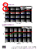
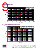
2 / 16 page  Preliminary Data Sheet #: TM012 Page 2 of 16 Rev: P06 Date: 05/20/ 02 © Copyright 2002 The Connor-Winfield Corp. All Rights Reserved Specifications subject to change without notice General Description Connor-Winfield’s STM-S3E timing module provides Stratum 3E synchronization for a complete system clock solution in a single module in accordance with GR-1244- CORE Issue 2, GR-253-CORE Issue 3, and ITU-T G.812 Option III. The STM-S3E provides a reliable network element clock reference to line cards used in TDM, PDH, SONET, and SDH application environments. Typical applications include digital cross talks, DSLAMs, ADMs, multiservice platforms, switches and routers. The STM-S3E meets 12 ppb Hold Over requirements over 0° – 70°C temperature range. The 5V power requirement will draw a maximum of 1.2 A during an initial start-up period and then drop to a typical current of 800 mA during normal operating conditions. It accepts two 8 kHz input references and can be manufactured to supply a fixed frequency from 1.544 MHz to 38.88 MHz. The STM-S3E offers 4 user selectable modes of operation, Reference 1, Reference 2, Hold Over and Free Run. Mode of operation is selected by two control pins (Table 6). The current mode of operation is also indicated by two status pins (Table 7). Free Run is the default mode if no control signals are asserted on the control pins. Reference 1 mode and Reference 2 mode are the two primary operating modes. When the module is locked to a valid reference, any time after initial power up or reset, the module is considered to be in the normal operating mode. During normal operation the output frequency is phase locked to the input reference frequency. The offset between the input and output is dependant upon the amount of noise that is present on the reference signal. For input tolerances, refer to Table 4. Hold Over mode provides a stable frequency that is guaranteed to be within ±0.012 ppm over the entire temperature range for the first 24 hours after entry into Hold Over. Hold Over is valid 701 seconds after a reference is selected and continues to do a running average every 8 seconds for the next 1049 seconds. Long-term Hold Over values are based on a 1049 second moving window average. Hold Over values are not updated during LOR or during Fast Acquisition mode. Hold Over values are buffered for at least 32 seconds to allow enough time to respond to the RFL alarm. Free Run is a mode of operation in which the module is not locked to a reference and its output frequency is solely dependent on the initial frequency setting of the internal oscillator. The output frequency in Free Run is guaranteed to be ±4.6ppm of the nominal frequency. A fifth, automatic mode of operation is Fast Acquisition mode. Fast Acquisition mode is entered whenever Reference 1 or 2 has been selected. After a new reference has been selected, the module uses internal filtering that limits the frequency movement to less than 2.9 ppm/sec. By 600 seconds the module switches to a slower 0.001Hz filter. While in normal mode, if the phase error is greater than 20 µs, Fast Acquisition mode will be initiated. Fast Acquisition mode is further described as fast start mode in GR-1244- CORE, Issue 3, sec 3.6. The STM-S3E may be reset by asserting a logic low signal to the Reset pin or cycling the power. Using the Reset pin for a manual reset is the recommend method for resetting the module. Resetting the module by cycling the power requires more time due to the restablization of the internal ovenized oscillator. The STM-S3E provides the user with non-interruptive Tri- State capabilities. By asserting a logic high signal to the Tri- State pin, the user is able to Tri-State all outputs. While in Tri-State, the module continues normal operations and accepts all normal inputs. When the module is released from Tri-State, all output signals are valid. The STM-S3E module provides three output frequencies. The Sync_Out is the primary synchronized output. It is phase locked to the input reference during normal operation and is set to a fixed frequency when operating in Hold Over or Free Run. Clock_Out provides a frequency output that comes from an independent, undisciplined, free running oscillator that is ±4.6 ppm from the nominal frequency. This output is typically used for reference frequency qualification. The 8 kHz output is derived from the Sync_Out output. The STM-S3E module provides a variety of alarm indicators to alert the user to multiple conditions that may affect the overall performance of their system. The LOR (Loss of Reference) alarm indicates that the active reference has been lost. RFL (Reference Frequency Limit) indicates that the Sync_Out frequency is 15 ppm or more from the Free Run frequency. The PBO (Phase Build Out) pin indicates that a phase transient greater than 3.4 µs over any 0.1 second interval has occurred. The PBO indicator will remain high as long as the phase transient condition exists. The Mode Alarm pin is used to indicate that the module is not in a normal operating mode. Conditions that will cause the Mode Alarm to go high are Hold Over, Free Run, Fast Acquisition Modes or when Phase Build Out has been active for more than 0.4 seconds. During the latter condition, both the Mode Alarm indicator and the PBO indicator will be high. See Table 8 for a full description of input control pins and output indicator pins. The Hold Over Good pin indicates that an initial average has been acquired to provide a qualified Hold Over frequency. The module requires approximately 700 seconds from any reference switch or mode switch to a new reference to reacquire a valid average before the indicator goes high (Fig. 17). Initially, entry into Hold Over prior to this will result in a Free Run frequency. After the first Hold Over Good indication, entry into Hold Over will be the last valid Hold Over frequency. The STM-S3E meets the requirements for wander generation and wander transfer as required by GR-1244, sections 5.3 and 5.4. Figures 4, 5 and 6 show typical results. It also complies with phase transient requirements during Reference Rearrangement, Entry into Hold Over, and 1 µs transient. See figures 7-9 for typical performance results and requirement masks. Input jitter is attenuated at about 20 dB/ decade to minimize jitter noise from being passed to other network elements or clocks. Figure 10 illustrates the STM- S3E’s typical roll off of attenuated jitter. |
|
|
链接网址 |
| ALLDATASHEET是否为您带来帮助? [ DONATE ] |
关于 Alldatasheet | 广告服务 | 联系我们 | 隐私政策 | 数据表链接 | 链接交换 | 制造商名单 All Rights Reserved©Alldatasheet.com |
| Russian : Alldatasheetru.com | Korean : Alldatasheet.co.kr | Spanish : Alldatasheet.es | French : Alldatasheet.fr | Italian : Alldatasheetit.com Portuguese : Alldatasheetpt.com | Polish : Alldatasheet.pl | Vietnamese : Alldatasheet.vn Indian : Alldatasheet.in | Mexican : Alldatasheet.com.mx | British : Alldatasheet.co.uk | New Zealand : Alldatasheet.co.nz |
|
Family Site : ic2ic.com |
icmetro.com |
 Chinese ▼
 English
 Chinese
 German
 Japanese
 Russian
 Korean
 Spanish
 French
 Italian
 Portuguese
 Polish
 Vietnamese
 Indian
 Mexican
 British
 New Zealand