|
数据搜索系统,热门电子元器件搜索 |
|
|
数据搜索系统,热门电子元器件搜索 |
|
ADL5356ACPZ-R7 数据表(PDF) 17 Page - Analog Devices |
|
|
|||||||||||||||||||||||||||||
ADL5356ACPZ-R7 数据表(HTML) 17 Page - Analog Devices |
|
|
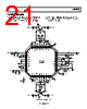
17 / 24 page  ADL5356 Rev. 0 | Page 17 of 24 CIRCUIT DESCRIPTION The ADL5356 consists of two primary components: the radio frequency (RF) subsystem and the local oscillator (LO) subsystem. The combination of design, process, and packaging technology allows the functions of these subsystems to be integrated into a single die using mature packaging and interconnection technologies to provide a high performance, low cost design with excellent electrical, mechanical, and thermal properties. In addition, the need for external components is minimized, optimizing cost and size. The resulting balanced RF signal is applied to a passive mixer that commutates the RF input with the output of the LO subsystem. The passive mixer is essentially a balanced, low loss switch that adds minimum noise to the frequency translation. The only noise contribution from the mixer is due to the resistive loss of the switches, which is in the order of a few ohms. Because the mixer is inherently broadband and bidirectional, it is necessary to properly terminate all the idler (M × N product) frequencies generated by the mixing process. Terminating the mixer avoids the generation of unwanted intermodulation products and reduces the level of unwanted signals at the input of the IF amplifier, where high peak signal levels can compromise the compression and intermodulation performance of the system. This termination is accomplished by the addition of a sum network between the IF amplifier and the mixer and in the feedback elements in the IF amplifier. The RF subsystem consists of integrated, low loss RF baluns, passive MOSFET mixers, sum termination networks, and IF amplifiers. The LO subsystem consists of an SPDT-terminated FET switch and two multistage limiting LO amplifiers. The purpose of the LO subsystem is to provide a large, fixed amplitude, balanced signal to drive the mixer independent of the level of the LO input. A block diagram of the device is shown in Figure 52. The IF amplifier is a balanced feedback design that simultaneously provides the desired gain, noise figure, and input impedance that is required to achieve the overall performance. The balanced open- collector output of the IF amplifier, with impedance modified by the feedback within the amplifier, permits the output to be connected directly to a high impedance filter, differential amplifier, or an analog-to-digital input while providing optimum second- order intermodulation suppression. The differential output impedance of the IF amplifier is approximately 200 Ω. If operation in a 50 Ω system is desired, the output can be transformed to 50 Ω by using a 4:1 transformer. 2 3 1 36 35 34 33 32 31 30 29 28 10 11 12 13 14 15 16 17 18 4 6 7 5 8 9 26 25 27 24 22 21 23 20 19 ADL5356 VGS0 VGS1 VGS2 LOSW PWDN VPOS COMM LOI2 LOI1 MNIN MNCT COMM DVIN VPOS COMM VPOS COMM DVCT The intermodulation performance of the design is generally limited by the IF amplifier. The IP3 performance can be optimized by adjusting the IF current with an external resistor. Figure 41, Figure 43, and Figure 44 illustrate how various IF and LO bias resistors affect the performance with a 5 V supply. Additionally, dc current can be saved by increasing either or both resistors. It is permissible to reduce the dc supply voltage to as low as 3.3 V, further reducing the dissipated power of the part. (No performance enhancement is obtained by reducing the value of these resistors, and excessive dc power dissipation may result.) Figure 52. Simplified Schematic RF SUBSYSTEM The single-ended, 50 Ω RF input is internally transformed to a balanced signal using a low loss (<1 dB) unbalanced-to-balanced (balun) transformer. This transformer is made possible by an extremely low loss metal stack, which provides both excellent balance and dc isolation for the RF port. Although the port can be dc connected, it is recommended that a blocking capacitor be used to avoid running excessive dc current through the part. The RF balun can easily support an RF input frequency range of 1200 MHz to 2500 MHz. |
|
|
链接网址 |
| ALLDATASHEET是否为您带来帮助? [ DONATE ] |
关于 Alldatasheet | 广告服务 | 联系我们 | 隐私政策 | 数据表链接 | 链接交换 | 制造商名单 All Rights Reserved©Alldatasheet.com |
| Russian : Alldatasheetru.com | Korean : Alldatasheet.co.kr | Spanish : Alldatasheet.es | French : Alldatasheet.fr | Italian : Alldatasheetit.com Portuguese : Alldatasheetpt.com | Polish : Alldatasheet.pl | Vietnamese : Alldatasheet.vn Indian : Alldatasheet.in | Mexican : Alldatasheet.com.mx | British : Alldatasheet.co.uk | New Zealand : Alldatasheet.co.nz |
|
Family Site : ic2ic.com |
icmetro.com |
 Chinese ▼
 English
 Chinese
 German
 Japanese
 Russian
 Korean
 Spanish
 French
 Italian
 Portuguese
 Polish
 Vietnamese
 Indian
 Mexican
 British
 New Zealand