|
数据搜索系统,热门电子元器件搜索 |
|
|
数据搜索系统,热门电子元器件搜索 |
|
LTC4150CMS 数据表(PDF) 8 Page - Linear Technology |
|
|
|||||||||||||||||||||||||||||
LTC4150CMS 数据表(HTML) 8 Page - Linear Technology |
|
|
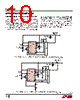
8 / 14 page  LTC4150 8 4150fc APPLICATIONS INFORMATION SENSE VOLTAGE INPUT AND FILTERS Since the overall integration time is set by internally trim- ming the LTC4150, no external timing capacitor or trimming is necessary. The only external component that affects the transfer function of interrupts per coulomb of charge is the sense resistor, RSENSE. The common mode range for the SENSE+ and SENSE– pins is VDD ±60mV, with a maximum differential voltage range of ±50mV. SENSE+ is normally tied to VDD, so there is no common mode issue when SENSE– operates within the 50mV differential limit relative to SENSE+. Choose RSENSE to provide 50mV drop at maximum charge or discharge current, whichever is greater. Calculate RSENSE from: R mV I SENSE MAX = 50 (1) The sense input range is small (±50mV) to minimize the loss across RSENSE. To preserve accuracy, use Kelvin connections at RSENSE. The external filter capacitor, CF, operates against a total on-chip resistance of 4k to form a lowpass filter that averages battery current and improves accuracy in the presence of noise, spikes and ripple. 4.7μF is recom- mended for general applications but can be extended to higher values as long as the capacitor’s leakage is low. A 10nA leakage is roughly equivalent to the input offset error of the integrator. Ceramic capacitors are suitable for this use. Switching regulators are a particular concern because they generate high levels of current ripple which may flow through the battery. The VDD and SENSE+ connection to the charger and load should be bypassed by at least 4.7μF at the LTC4150 if a switching regulator is present. The LTC4150 maintains high accuracy even when Burst Mode ® switching regulators are used. Burst pulse “on” levels must be within the specified differential input volt- age range of 50mV as measured at CF+ and CF–. To retain accurate charge information, the LTC4150 must remain enabled during Burst Mode operation. If the LTC4150 shuts down or VDD drops below 2.5V, the part resets and charge information is lost. Coulomb Counting The LTC4150’s transfer function is quantified as a volt- age to frequency gain GVF, where output frequency is the number of interrupts per second and input voltage is the differential drive VSENSE across SENSE+ and SENSE–. The number of interrupts per second will be: f = GVF • ⏐VSENSE⏐ (2) where VSENSE = IBATTERY • RSENSE (3) Therefore, f = GVF • ⏐IBATTERY • RSENSE⏐ (4) Since I • t = Q, coulombs of battery charge per INT pulse can be derived from Equation 4: One INT GR Coulombs VF SENSE = 1 • (5) Battery capacity is most often expressed in ampere- hours. 1Ah = 3600 Coulombs (6) Combining Equations 5 and 6: One INT GR VF SENSE = 1 3600 • • [Ah] (7) or 1Ah = 3600 • GVF • RSENSE Interrupts (8) The charge measurement may be further scaled within the microcontroller. However, the number of interrupts, coulombs or Ah all represent battery charge. The LTC4150’s transfer function is set only by the value of the sense resistor and the gain GVF. Once RSENSE is selected using Equation 1, the charge per interrupt can be determined from Equation 5 or 7. Note that RSENSE is not chosen to set the relationship between ampere-hours of battery charge and number of interrupts issued by the LTC4150. Rather, RSENSEischosen to keep the maximum sense voltage equal to or less than the LTC4150’s 50mV full-scale sense input. |
|
|
链接网址 |
| ALLDATASHEET是否为您带来帮助? [ DONATE ] |
关于 Alldatasheet | 广告服务 | 联系我们 | 隐私政策 | 数据表链接 | 链接交换 | 制造商名单 All Rights Reserved©Alldatasheet.com |
| Russian : Alldatasheetru.com | Korean : Alldatasheet.co.kr | Spanish : Alldatasheet.es | French : Alldatasheet.fr | Italian : Alldatasheetit.com Portuguese : Alldatasheetpt.com | Polish : Alldatasheet.pl | Vietnamese : Alldatasheet.vn Indian : Alldatasheet.in | Mexican : Alldatasheet.com.mx | British : Alldatasheet.co.uk | New Zealand : Alldatasheet.co.nz |
|
Family Site : ic2ic.com |
icmetro.com |
 Chinese ▼
 English
 Chinese
 German
 Japanese
 Russian
 Korean
 Spanish
 French
 Italian
 Portuguese
 Polish
 Vietnamese
 Indian
 Mexican
 British
 New Zealand