|
数据搜索系统,热门电子元器件搜索 |
|
|
数据搜索系统,热门电子元器件搜索 |
|
LTC4150CMS 数据表(PDF) 5 Page - Linear Technology |
|
|
|||||||||||||||||||||||||||||
LTC4150CMS 数据表(HTML) 5 Page - Linear Technology |
|
|
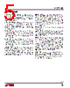
5 / 14 page  LTC4150 5 4150fc PIN FUNCTIONS SENSE+ (Pin 1): Positive Sense Input. This is the nonin- verting current sense input. Connect SENSE+ to the load and charger side of the sense resistor. Full-scale current sense input is 50mV. SENSE+ must be within 60mV of VDD for proper operation. SENSE– (Pin 2): Negative Sense Input. This is the inverting current sense input. Connect SENSE– to the positive bat- tery terminal side of the sense resistor. Full-scale current sense input is 50mV. SENSE– must be within 60mV of VDD for proper operation. CF+ (Pin 3): Filter Capacitor Positive Input. A capacitor connected between CF+ and CF– filters and averages noise and fast battery current variations. A 4.7μF value is recommended. If filtering is not desired, leave CF+ and CF– unconnected. CF– (Pin 4): Filter Capacitor Negative Input. A capacitor connected between CF+ and CF– filters and averages noise and fast battery current variations. A 4.7μF value is recommended. If filtering is not desired, leave CF+ and CF– unconnected. SHDN(Pin5):ShutdownDigitalInput.Whenassertedlow, SHDNforcestheLTC4150intoitslowcurrentconsumption power-down mode and resets the part. In applications with logic supply VCC > VDD, a resistive divider must be used between SHDN and the logic which drives it. See the Applications Information section. POL (Pin 6): Battery Current Polarity Open-Drain Output. POL indicates the most recent battery current polarity when INT is high. A low state indicates the current is flowing out of the battery while high impedance means the current is going into the battery. POL latches its state when INT is asserted low. POL is an open-drain output and can be pulled up to any logic supply up to 9V. In shutdown, POL is high impedance. GND (Pin 7): Ground. Connect directly to the negative battery terminal. VDD (Pin 8): Positive Power Supply. Connect to the load and charger side of the sense resistor. SENSE+ also con- nects to VDD. VDD operating range is 2.7V to 8.5V. Bypass VDD with 4.7μF capacitor. CLR (Pin 9): Clear Interrupt Digital Input. When asserted low for more than 20μs, CLR resets INT high. Charge counting is unaffected. INT may be directly connected to CLR. In this case the LTC4150 will capture each assertion of INT and wait at least 1μs before resetting it. This ensures that INT pulses low for at least 1μs but gives automatic INT reset. In applications with a logic supply VCC > VDD, a resistive divider must be used between INT and CLR. See the Applications Information section. INT (Pin 10): Charge Count Interrupt Open-Drain Output. INT latches low every 1/(VSENSE • GVF) seconds and is reset by a low pulse at CLR. INT is an open-drain output and can be pulled up to any logic supply of up to 9V. In shutdown INT is high impedance. |
|
|
链接网址 |
| ALLDATASHEET是否为您带来帮助? [ DONATE ] |
关于 Alldatasheet | 广告服务 | 联系我们 | 隐私政策 | 数据表链接 | 链接交换 | 制造商名单 All Rights Reserved©Alldatasheet.com |
| Russian : Alldatasheetru.com | Korean : Alldatasheet.co.kr | Spanish : Alldatasheet.es | French : Alldatasheet.fr | Italian : Alldatasheetit.com Portuguese : Alldatasheetpt.com | Polish : Alldatasheet.pl | Vietnamese : Alldatasheet.vn Indian : Alldatasheet.in | Mexican : Alldatasheet.com.mx | British : Alldatasheet.co.uk | New Zealand : Alldatasheet.co.nz |
|
Family Site : ic2ic.com |
icmetro.com |
 Chinese ▼
 English
 Chinese
 German
 Japanese
 Russian
 Korean
 Spanish
 French
 Italian
 Portuguese
 Polish
 Vietnamese
 Indian
 Mexican
 British
 New Zealand