|
数据搜索系统,热门电子元器件搜索 |
|
|
数据搜索系统,热门电子元器件搜索 |
|
LPC2157 数据表(PDF) 8 Page - NXP Semiconductors |
|
|
|||||||||||||||||||||||||||||
LPC2157 数据表(HTML) 8 Page - NXP Semiconductors |
|
|
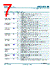
8 / 45 page  LPC2157_2158_2 © NXP B.V. 2009. All rights reserved. Product data sheet Rev. 02 — 9 February 2009 8 of 45 NXP Semiconductors LPC2157/2158 Single-chip 16-bit/32-bit microcontrollers P0[27]/AD0[0]/ CAP0[1]/MAT0[1] 99[7] I/O P0[27] — General purpose input/output digital pin (GPIO). I AD0[0] — ADC 0, input 0. This analog input is always connected to its pin. I CAP0[1] — Capture input for Timer 0, channel 1. O MAT0[1] — Match output for Timer 0, channel 1. P0[28]/AD0[1]/ CAP0[2]/MAT0[2] 1[4] I/O P0[28] — General purpose input/output digital pin (GPIO). I AD0[1] — ADC 0, input 1. I CAP0[2] — Capture input for Timer 0, channel 2. O MAT0[2] — Match output for Timer 0, channel 2. P0[29]/AD0[2]/ CAP0[3]MAT0[3] 2[4] I/O P0[29] — General purpose input/output digital pin (GPIO). I AD0[2] — ADC 0, input 2. I CAP0[3] — Capture input for Timer 0, channel 3. O MAT0[3] — Match output for Timer 0, channel 3. P0[30]/AD0[3]/ EINT3/CAP0[0] 3[4] I/O P0[30] — General purpose input/output digital pin (GPIO). I AD0[3] — ADC 0, input 3. I EINT3 — External interrupt 3 input. I CAP0[0] — Capture input for Timer 0, channel 0. P0[31] 5[6] O P0[31] — General purpose output only digital pin. P1[0] to P1[31] I/O Port 1: Port 1 is a 32-bit bidirectional I/O port with individual direction controls for each bit. The operation of port 1 pins depends upon the pin function selected via the pin connect block. Pins 0 through 15 and 18 through 24 of port 1 are not available. P1[16] 4[6] I/O P1[16] — General purpose input/output digital pin (GPIO). P1[17] 100[6] I/O P1[17] — General purpose input/output digital pin (GPIO). P1[25]/EXTIN0 16[6] I/O P1[25] — General purpose input/output digital pin (GPIO). I EXTIN0 — External Trigger Input. Standard I/O with internal pull-up. P1[26]/RTCK 12[6] I/O P1[26] — General purpose input/output digital pin (GPIO). I/O RTCK — Returned Test Clock output. Extra signal added to the JTAG port. Assists debugger synchronization when processor frequency varies. Bidirectional pin with internal pull-up. Note: LOW on RTCK while RESET is LOW enables pins P1[31:26] to operate as Debug port after reset. P1[27]/TDO 90[6] I/O P1[27] — General purpose input/output digital pin (GPIO). O TDO — Test Data out for JTAG interface. P1[28]/TDI 86[6] I/O P1[28] — General purpose input/output digital pin (GPIO). I TDI — Test Data in for JTAG interface. P1[29]/TCK 82[6] I/O P1[29] — General purpose input/output digital pin (GPIO). I TCK — Test Clock for JTAG interface. This clock must be slower than 1 ⁄6 of the CPU clock (CCLK) for the JTAG interface to operate. P1[30]/TMS 78[6] I/O P1[30] — General purpose input/output digital pin (GPIO). I TMS — Test Mode Select for JTAG interface. P1[31]/TRST 8[6] I/O P1[31] — General purpose input/output digital pin (GPIO). I TRST — Test Reset for JTAG interface. Table 2. Pin description LPC2157 …continued Symbol Pin Type Description |
|
链接网址 |
| ALLDATASHEET是否为您带来帮助? [ DONATE ] |
关于 Alldatasheet | 广告服务 | 联系我们 | 隐私政策 | 数据表链接 | 链接交换 | 制造商名单 All Rights Reserved©Alldatasheet.com |
| Russian : Alldatasheetru.com | Korean : Alldatasheet.co.kr | Spanish : Alldatasheet.es | French : Alldatasheet.fr | Italian : Alldatasheetit.com Portuguese : Alldatasheetpt.com | Polish : Alldatasheet.pl | Vietnamese : Alldatasheet.vn Indian : Alldatasheet.in | Mexican : Alldatasheet.com.mx | British : Alldatasheet.co.uk | New Zealand : Alldatasheet.co.nz |
|
Family Site : ic2ic.com |
icmetro.com |
 Chinese ▼
 English
 Chinese
 German
 Japanese
 Russian
 Korean
 Spanish
 French
 Italian
 Portuguese
 Polish
 Vietnamese
 Indian
 Mexican
 British
 New Zealand