|
数据搜索系统,热门电子元器件搜索 |
|
|
数据搜索系统,热门电子元器件搜索 |
|
AD8494ARMZ-R7 数据表(PDF) 13 Page - Analog Devices |
|
|
|||||||||||||||||||||||||||||
AD8494ARMZ-R7 数据表(HTML) 13 Page - Analog Devices |
|
|
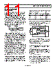
13 / 16 page  AD8494/AD8495/AD8496/AD8497 Rev. 0 | Page 13 of 16 Keeping the AD849x at the Same Temperature as the Reference Junction RECOMMENDATIONS FOR BEST CIRCUIT PERFORMANCE The AD849x compensates for thermocouple reference junction temperature by using an internal temperature sensor. It is critical to keep the reference junction (thermocouple-to-PCB connection) as close to the AD849x as possible. Any difference in temperature between the AD849x and the reference junction appears directly as temperature error. Temperature difference between the device and the reference junction may occur if the AD849x is not physically close to the reference junction or if the AD849x is required to supply large amounts of output power. Input Filter A low-pass filter before the input of the AD849x is strongly recommended (see Figure 29), especially when operating in an electrically noisy environment. Long thermocouple leads can function as an excellent antenna and pick up many unwanted signals. The filter should be set to a low corner frequency that still allows the input signal to pass through undiminished. The primary purpose of the filter is to remove RF signals, which, if allowed to reach the AD849x, can be rectified and appear as temperature fluctuations. AD849x PCB TRACES KEEP TRACES SHORT KEEP JUNCTION AND AD849x AT SAME TEMPERATURE MEASUREMENT JUNCTION REFERENCE JUNCTION THERMOCOUPLE WIRES R R AD849x CD CC CC 1M Ω CONNECT WHEN THERMOCOUPLE TIP TYPE IS UNKNOWN FILTER FREQUENCYDIFF = 1 2 πR(2CD + CC) FILTER FREQUENCYCM = WHERE CD ≥ 10CC 1 2 πRCC Figure 31. Compensating for Thermocouple Reference Junction Temperature Driving the Reference Pin The AD849x comes with a reference pin, which can be used to offset the output voltage. This is particularly useful when reading a negative temperature in a single-supply system. INCORRECT V CORRECT AD849x AD8613 + – V REF AD849x REF Figure 29. Filter for Any Thermocouple Style To prevent input offset currents from affecting the measurement accuracy, the filter resistor values should be less than 50 kΩ. Ground Connection It is always recommended that the thermocouple be connected to ground through a 100 kΩ to 1 MΩ resistor placed at the negative (inverting) input of the amplifier on the PCB (see Figure 30). This solution works well regardless of the thermo- couple tip style. 1M Ω Figure 32. Driving the Reference Pin For best performance, the reference pin should be driven with a low output impedance source, not a resistor divider. The AD8613 and the OP777 are good choices for the buffer amplifier. Figure 30. Ground the Thermocouple with a 1 MΩ Resistor Debugging Tip If there is no electrical connection at the measurement junction (insulated tip), the resistor value is small enough that no mean- ingful common-mode voltage is generated. If there is an electrical connection through a grounded or exposed tip, the resistor value is large enough that any current from the measurement tip to ground is very small, preventing measurement errors. If the AD849x is not providing the expected performance, a useful debugging step is to implement the ambient temperature configuration in Figure 34. If the ambient temperature sensor does not work as expected, the problem is likely with the AD849x or with the downstream circuitry. If the ambient temperature sensor configuration is working correctly, the problem typically lies with how the thermocouple is connected to the AD849x. Common errors include an incorrect grounding configuration or lack of filtering. The AD849x inputs require only one ground connection or source of common-mode voltage. Any additional ground connection is detrimental to performance because ground loops can form through the thermocouple, easily swamping the small thermocouple signal. Grounding the thermocouple through a resistor as recommended prevents such problems. |
|
|
链接网址 |
| ALLDATASHEET是否为您带来帮助? [ DONATE ] |
关于 Alldatasheet | 广告服务 | 联系我们 | 隐私政策 | 数据表链接 | 链接交换 | 制造商名单 All Rights Reserved©Alldatasheet.com |
| Russian : Alldatasheetru.com | Korean : Alldatasheet.co.kr | Spanish : Alldatasheet.es | French : Alldatasheet.fr | Italian : Alldatasheetit.com Portuguese : Alldatasheetpt.com | Polish : Alldatasheet.pl | Vietnamese : Alldatasheet.vn Indian : Alldatasheet.in | Mexican : Alldatasheet.com.mx | British : Alldatasheet.co.uk | New Zealand : Alldatasheet.co.nz |
|
Family Site : ic2ic.com |
icmetro.com |
 Chinese ▼
 English
 Chinese
 German
 Japanese
 Russian
 Korean
 Spanish
 French
 Italian
 Portuguese
 Polish
 Vietnamese
 Indian
 Mexican
 British
 New Zealand