|
数据搜索系统,热门电子元器件搜索 |
|
|
数据搜索系统,热门电子元器件搜索 |
|
ADR3450ARJZ-R7 数据表(PDF) 14 Page - Analog Devices |
|
|
|||||||||||||||||||||||||||||
ADR3450ARJZ-R7 数据表(HTML) 14 Page - Analog Devices |
|
|
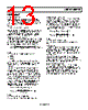
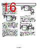
14 / 20 page  ADR3425/ADR3450 Rev. 0 | Page 14 of 20 THEORY OF OPERATION BANDGAP VOLTAGE REFERENCE ENABLE GND FORCE REF FORCE REF SENSE RFB2 RFB1 VDD VBG GND SENSE Figure 39. Block Diagram The ADR342 5/ADR3450 use a patented voltage reference architecture to achieve high accuracy, low temperature coefficient (TC), and low noise in a CMOS process. Like all bandgap references, the ADR3425/ADR3450 combine two voltages of opposite TCs to create an output voltage that is nearly independent of ambient temperature. However, unlike traditional bandgap voltage references, the temperature- independent voltage of the ADR3425/ADR3450 are arranged to be the base-emitter voltage, VBE, of a bipolar transistor at room temperature rather than the VBE extrapolated to 0 K (the VBE of bipolar transistor at 0 K is approximately VG0, the band gap voltage of silicon). A corresponding positive-TC voltage is then added to the VBE voltage to compensate for its negative TC. The key benefit of this technique is that the trimming of the initial accuracy and TC can be performed without interfering with one another, thereby increasing overall accuracy across temperature. Curvature correction techniques further reduce the temperature variation. The bandgap voltage is then buffered and amplified to produce stable output voltages of 2.5 V and 5.0 V. The output buffer can source up to 10 mA and sink up to 3 mA of load current. The ADR3425/ADR3450 leverage Analog Devices patented DigiTrim technology to achieve high initial accuracy and low TC, while precision layout techniques lead to very low long-term drift and thermal hysteresis. LONG-TERM STABILITY One of the key parameters of the ADR3425/ADR3450 references is long-term stability. Regardless of output voltage, internal testing during development showed a typical drift of approximately 30 ppm after 1,000 hours of continuous, non loaded operation in a +50°C environment. It is important to understand that long-term stability is not guaranteed by design and that the output from the device may shift beyond the typical 30 ppm specification at any time, especially during the first 200 hours of operation. For systems that require highly stable output voltages over long periods of time, the designer should consider burning-in the devices prior to use to minimize the amount of output drift exhibited by the reference over time. See the AN-713 Application Note for more information regarding the effects of long-term drift and how it can be minimized. POWER DISSIPATION The ADR3425/ADR3450 voltage references are capable of sourcing up to 10 mA of load current at room temperature across the rated input voltage range. However, when used in applications subject to high ambient temperatures, the input voltage and load current should be carefully monitored to ensure that the device does not exceeded its maximum power dissipation rating. The maximum power dissipation of the device can be calculated via the following equation: ] [W T T P JA A J D θ − = where: PD is the device power dissipation. TJ is the device junction temperature. TA is the ambient temperature. θJA is the package (junction-to-air) thermal resistance. Because of this relationship, acceptable load current in high temperature conditions may be less than the maximum current- sourcing capability of the device. In no case should the part be operated outside of its maximum power rating because doing so can result in premature failure or permanent damage to the device. |
|
|
链接网址 |
| ALLDATASHEET是否为您带来帮助? [ DONATE ] |
关于 Alldatasheet | 广告服务 | 联系我们 | 隐私政策 | 数据表链接 | 链接交换 | 制造商名单 All Rights Reserved©Alldatasheet.com |
| Russian : Alldatasheetru.com | Korean : Alldatasheet.co.kr | Spanish : Alldatasheet.es | French : Alldatasheet.fr | Italian : Alldatasheetit.com Portuguese : Alldatasheetpt.com | Polish : Alldatasheet.pl | Vietnamese : Alldatasheet.vn Indian : Alldatasheet.in | Mexican : Alldatasheet.com.mx | British : Alldatasheet.co.uk | New Zealand : Alldatasheet.co.nz |
|
Family Site : ic2ic.com |
icmetro.com |
 Chinese ▼
 English
 Chinese
 German
 Japanese
 Russian
 Korean
 Spanish
 French
 Italian
 Portuguese
 Polish
 Vietnamese
 Indian
 Mexican
 British
 New Zealand