|
数据搜索系统,热门电子元器件搜索 |
|
|
数据搜索系统,热门电子元器件搜索 |
|
ADR3450ARJZ-R7 数据表(PDF) 15 Page - Analog Devices |
|
|
|||||||||||||||||||||||||||||
ADR3450ARJZ-R7 数据表(HTML) 15 Page - Analog Devices |
|
|
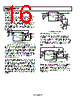
15 / 20 page  ADR3425/ADR3450 Rev. 0 | Page 15 of 20 APPLICATIONS BASIC VOLTAGE REFERENCE CONNECTION VIN 2.7V TO 5.5V VREF OUT 2.5V 0.1µF 1µF 0.1µF ADR3425 VIN ENABLE VOUT FORCE VOUT SENSE GND FORCE GND SENSE 4 3 6 5 2 1 Figure 40. Basic Reference Connection The circuit shown in Figure 40 illustrates the basic configuration for the ADR3425/ADR3450. Bypass capacitors should be connected according to the guidelines below. INPUT AND OUTPUT CAPACITORS A 1 μF to 10 μF electrolytic or ceramic capacitor can be connected to the input to improve transient response in applications where the supply voltage may fluctuate. An additional 0.1 μF ceramic capacitor should be connected in parallel to reduce high frequency supply noise. A ceramic capacitor of at least a 0.1 μF must be connected to the output to improve stability and help filter out high frequency noise. An additional 1 μF to 10 μF electrolytic or ceramic capacitor can be added in parallel to improve transient performance in response to sudden changes in load current; however, the designer should keep in mind that doing so increases the turn-on time of the device. Best performance and stability is attained with low-ESR (for example, less than 1 Ω), low-inductance ceramic chip-type output capacitors (X5R, X7R or similar). If using an electrolytic capacitor on the output, a 0.1 μF ceramic capacitor should be placed in parallel to reduce overall ESR on the output. 4-WIRE KELVIN CONNECTIONS Current flowing through a PCB trace produces an IR voltage drop, and with longer traces, this drop can reach several millivolts or more, introducing a considerable error into the output voltage of the reference. A 1 inch long, 5 millimeter wide trace of 1 ounce copper has a resistance of approximately 100 mΩ at room temperature; at a load current of 10 mA, this can introduce a full millivolt of error. In an ideal board layout, the reference should be mounted as close to the load as possible to minimize the length of the output traces, and, therefore, the error introduced by voltage drop. However, in applications where this is not possible or convenient, force and sense connections (sometimes referred to as Kelvin sensing connections) are provided as a means of minimizing the IR drop and improving accuracy. Kelvin connections work by providing a set of high impedance voltage-sensing lines to the output and ground nodes. Because very little current flows through these connections, the IR drop across their traces is negligible, and the output and ground voltages can be sensed very accurately. These voltages are fed back into the internal amplifier and used to automatically correct for the voltage drop across the current-carrying output and ground lines, resulting in a highly accurate output voltage across the load. To achieve the best performance, the sense connections should be connected directly to the point in the load where the output voltage should be the most accurate. See Figure 41 for an example application. LOAD VIN 0.1µF 0.1µF 1µF OUTPUT CAPACITOR(S) SHOULD BE MOUNTED AS CLOSE TO VOUT PIN AS POSSIBLE. SENSE CONNECTIONS SHOULD CONNECT AS CLOSE TO LOAD DEVICE AS POSSIBLE. ADR3425 VIN ENABLE VOUT FORCE VOUT SENSE GND FORCE GND SENSE 4 3 6 5 2 1 Figure 41. Application Showing Kelvin Connection It is always advantageous to use Kelvin connections whenever possible. However, in applications where the IR drop is negligible or an extra set of traces cannot be routed to the load, the force and sense pins for both VOUT and GND can simply be tied together and the device can be used in the same fashion as a normal 3-terminal reference (as shown in Figure 40). VIN SLEW RATE CONSIDERATIONS In applications with slow-rising input voltage signals, the reference exhibits overshoot or other transient anomalies that appear on the output. These phenomena also appear during shutdown as the internal circuitry loses power. To avoid such conditions, ensure that the input voltage waveform has both a rising and falling slew rate of at least 0.1 V/ms. SHUTDOWN/ENABLE FEATURE The ADR3425/ADR3450 references can be switched to a low- power shutdown mode when a voltage of 0.7 V or lower is input to the ENABLE pin. Likewise, the reference becomes operational for ENABLE voltages of 0.85 × VIN or higher. During shutdown, the supply current drops to less than 5 μA, useful in applications that are sensitive to power consumption. If using the shutdown feature, ensure that the ENABLE pin voltage does not fall between 0.7 V and 0.85 × VIN because this causes a large increase in the supply current of the device and may keep the reference from starting up correctly (see Figure 34). If not using the shutdown feature, however, the ENABLE pin can simply be tied to the VIN pin, and the reference remains operational continuously. |
|
|
链接网址 |
| ALLDATASHEET是否为您带来帮助? [ DONATE ] |
关于 Alldatasheet | 广告服务 | 联系我们 | 隐私政策 | 数据表链接 | 链接交换 | 制造商名单 All Rights Reserved©Alldatasheet.com |
| Russian : Alldatasheetru.com | Korean : Alldatasheet.co.kr | Spanish : Alldatasheet.es | French : Alldatasheet.fr | Italian : Alldatasheetit.com Portuguese : Alldatasheetpt.com | Polish : Alldatasheet.pl | Vietnamese : Alldatasheet.vn Indian : Alldatasheet.in | Mexican : Alldatasheet.com.mx | British : Alldatasheet.co.uk | New Zealand : Alldatasheet.co.nz |
|
Family Site : ic2ic.com |
icmetro.com |
 Chinese ▼
 English
 Chinese
 German
 Japanese
 Russian
 Korean
 Spanish
 French
 Italian
 Portuguese
 Polish
 Vietnamese
 Indian
 Mexican
 British
 New Zealand