|
数据搜索系统,热门电子元器件搜索 |
|
|
数据搜索系统,热门电子元器件搜索 |
|
M95128-RMB6G/P 数据表(PDF) 11 Page - STMicroelectronics |
|
|
|||||||||||||||||||||||||||||
M95128-RMB6G/P 数据表(HTML) 11 Page - STMicroelectronics |
|
|
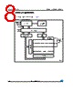
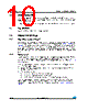
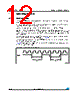
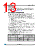
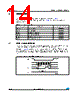
11 / 44 page  M95128, M95128-W, M95128-R Signal description Doc ID 5798 Rev 13 11/44 3.8.3 Power-up conditions When the power supply is turned on, VCC continuously rises from VSS to VCC. During this time, the Chip Select (S) line is not allowed to float but should follow the VCC voltage. It is therefore recommended to connect the S line to VCC via a suitable pull-up resistor (see Figure 12). In addition, the Chip Select (S) input offers a built-in safety feature, as it is edge-sensitive as well as level-sensitive: after power-up, the device does not become selected until a falling edge has first been detected on Chip Select (S). This ensures that Chip Select (S) must have been high, prior to going low to start the first operation. The VCC voltage has to rise continuously from 0 V up to the minimum VCC operating voltage defined in Table 7, Table 8 and Table 9 and the rise time must not vary faster than 1 V/µs. 3.8.4 Power-down During power-down (continuous decrease in the VCC supply voltage below the minimum VCC operating voltage defined in Table 7, Table 8 and Table 9), the device must be: ● deselected (Chip Select S should be allowed to follow the voltage applied on VCC) ● in Standby Power mode (there should not be any internal write cycle in progress). |
|
链接网址 |
| ALLDATASHEET是否为您带来帮助? [ DONATE ] |
关于 Alldatasheet | 广告服务 | 联系我们 | 隐私政策 | 数据表链接 | 链接交换 | 制造商名单 All Rights Reserved©Alldatasheet.com |
| Russian : Alldatasheetru.com | Korean : Alldatasheet.co.kr | Spanish : Alldatasheet.es | French : Alldatasheet.fr | Italian : Alldatasheetit.com Portuguese : Alldatasheetpt.com | Polish : Alldatasheet.pl | Vietnamese : Alldatasheet.vn Indian : Alldatasheet.in | Mexican : Alldatasheet.com.mx | British : Alldatasheet.co.uk | New Zealand : Alldatasheet.co.nz |
|
Family Site : ic2ic.com |
icmetro.com |
 Chinese ▼
 English
 Chinese
 German
 Japanese
 Russian
 Korean
 Spanish
 French
 Italian
 Portuguese
 Polish
 Vietnamese
 Indian
 Mexican
 British
 New Zealand