|
数据搜索系统,热门电子元器件搜索 |
|
|
数据搜索系统,热门电子元器件搜索 |
|
M24LR64-R 数据表(PDF) 27 Page - STMicroelectronics |
|
|
|||||||||||||||||||||||||||||
M24LR64-R 数据表(HTML) 27 Page - STMicroelectronics |
|
|
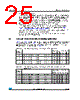
27 / 128 page  M24LR64-R System memory area Doc ID 15170 Rev 10 27/128 4.5 M24LR64-R I2C password security The M24LR64-R controls I2C sector write access using the 32-bit-long I2C password and the 64-bit I2C_Write_Lock bit area. The I2C password value is managed using two I2C commands: I2C Present Password and I2C Write Password. 4.5.1 I2C Present Password command description The I2C Present Password command is used in I2C mode to present the password to the M24LR64-R in order to modify the write access rights of all the memory sectors protected by the I2C_Write_Lock bits, including the password itself. If the presented password is correct, the access rights remain activated until the M24LR64-R is powered off or until a new I2C Present Password command is issued. Following a Start condition, the bus master sends a device select code with the Read/Write bit (RW) reset to 0 and the Chip Enable bit E2 at 1. The device acknowledges this, as shown in Figure 8, and waits for two I2C password address bytes 09h and 00h. The device responds to each address byte with an acknowledge bit, and then waits for the 4 password data bytes, the validation code, 09h, and a resend of the 4 password data bytes. The most significant byte of the password is sent first, followed by the least significant bytes. It is necessary to send the 32-bit password twice to prevent any data corruption during the sequence. If the two 32-bit passwords sent are not exactly the same, the M24LR64-R does not start the internal comparison. When the bus master generates a Stop condition immediately after the Ack bit (during the “10th bit” time slot), an internal delay equivalent to the write cycle time is triggered. A Stop condition at any other time does not trigger the internal delay. During that delay, the M24LR64-R compares the 32 received data bits with the 32 bits of the stored I2C password. If the values match, the write access rights to all protected sectors are modified after the internal delay. If the values do not match, the protected sectors remains protected. During the internal delay, Serial Data (SDA) is disabled internally, and the device does not respond to any requests. Table 14. System parameter sector I2C byte address Bits [31:24] Bits [23:16] Bits [15:8] Bits [7:0] E2 = 1 2304 I2C password (1) 1. Delivery state: I2C password= 0000 0000h, RF password = 0000 0000h, E2 = 1 2308 RF password 1(1) E2 = 1 2312 RF password 2(1) E2 = 1 2316 RF password 3 (1) E2 = 1 2320 DSFID (FFh) AFI (00h) ST reserved ST reserved E2 = 1 2324 UID UID UID UID E2 = 1 2328 UID (E0h) UID (02h) UID UID E2 = 1 2332 Mem_Size (03 07FFh) IC Ref (2Ch) |
|
链接网址 |
| ALLDATASHEET是否为您带来帮助? [ DONATE ] |
关于 Alldatasheet | 广告服务 | 联系我们 | 隐私政策 | 数据表链接 | 链接交换 | 制造商名单 All Rights Reserved©Alldatasheet.com |
| Russian : Alldatasheetru.com | Korean : Alldatasheet.co.kr | Spanish : Alldatasheet.es | French : Alldatasheet.fr | Italian : Alldatasheetit.com Portuguese : Alldatasheetpt.com | Polish : Alldatasheet.pl | Vietnamese : Alldatasheet.vn Indian : Alldatasheet.in | Mexican : Alldatasheet.com.mx | British : Alldatasheet.co.uk | New Zealand : Alldatasheet.co.nz |
|
Family Site : ic2ic.com |
icmetro.com |
 Chinese ▼
 English
 Chinese
 German
 Japanese
 Russian
 Korean
 Spanish
 French
 Italian
 Portuguese
 Polish
 Vietnamese
 Indian
 Mexican
 British
 New Zealand