|
数据搜索系统,热门电子元器件搜索 |
|
|
数据搜索系统,热门电子元器件搜索 |
|
ADL5202ACPZ-R7 数据表(PDF) 18 Page - Analog Devices |
|
|
|||||||||||||||||||||||||||||
ADL5202ACPZ-R7 数据表(HTML) 18 Page - Analog Devices |
|
|
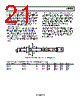
18 / 32 page  ADL5202 Data Sheet Rev. 0 | Page 18 of 32 CIRCUIT DESCRIPTION BASIC STRUCTURE The ADL5202 is a dual, differential, variable gain amplifier, with each amplifier consisting of a 150 Ω digitally controlled, passive attenuator that is followed by a highly linear transconductance amplifier with feedback. ATTENUATOR LOGIC REF VIN+ VIN– VOUT+ VOUT– DIGITAL INPUTS PARALLEL, SPI, FAST ATTACK UP/DOWN 1/2 OF ADL5202 gm AMP Figure 53. Simplified Schematic Input System The dc voltage level at the inputs of each amplifier is set by two independent internal voltage reference circuits to approximately 1.6 V. The references are not accessible and cannot be adjusted. Each amplifier can be powered down by pulling the correspond- ing power-up pin down to ground (logic low). When powered down, the total current of each amplifier reduces to 7 mA (typical). The dc level at the inputs remains at approximately 1.6 V, regardless of the state of the PWUPA or PWUPB pin. Output Amplifier The gain of the output amplifier is set to 22 dB when driving a 150 Ω load. The input and output resistance of this amplifier is set to 150 Ω in matched condition. If the load or the source resistance is different from 150 Ω, the following equations can be used to determine the resulting gain and input/output resistances. Voltage Gain = AV = 0.09 × (2000)//RL RIN = (2000 + RL)/(1 + 0.09 × RL) S21 (Gain) = 2 × RIN/(RIN + RS) × AV ROUT = (2000 + RS)/(1 + 0.09 × RS) Note that at the maximum attenuation setting, RS, as seen by the output amplifier, is the output resistance of the attenuator, which is 150 Ω. However, at minimum attenuation, RS is the source resistance that is connected to the input of the part. The dc current to the outputs of each amplifier is supplied through two external chokes. The inductance of the chokes and the resistance of the load, in parallel with the output resistance of the device, add a low frequency pole to the response. The para- sitic capacitance of the chokes adds to the output capacitance of the part. This total capacitance, in parallel with the load and output resistance, sets the high frequency pole of the device. Generally, the larger the inductance of the choke, the higher its parasitic capacitance. Therefore, this trade-off must be considered when the value and type of the choke are selected. For an operation frequency of 15 MHz to 700 MHz driving a 150 Ω load, 1 μH chokes with a self resonant frequency (SRF) of 160 MHz or higher are recommended (such as the 0805LS-102XJBB from Coilcraft). If higher value chokes are used, a 4 MHz zero, due to the internal ac-coupled feedback, causes an increase in S21 of up to 6 dB at frequencies below 4 MHz. The supply current of each amplifier consists of about 35 mA through the VPOS pin and 50 mA through the two chokes combined. The latter increases with temperature at approximately 2.5 mA per 10°C. The total choke current increases to 75 mA for high performance mode. Each amplifier has two output pins for each polarity, and they are oriented in an alternating fashion. When designing the board, care should be taken to minimize the parasitic capacitance due to the routing that connects the corresponding outputs together. To minimize the parasitic capacitance, a good practice is to avoid any ground or power plane under this routing region and under the chokes. Gain Control The gain of each amplifier can be adjusted using the parallel control interface, the serial peripheral interface, or the gain up/down interface. In general, the gain step size is 0.5 dB, but larger sizes can be programmed using the various interfaces, as described in the Digital Interface Overview section. Each amplifier has a maximum gain of +20 dB (Code 0) to −11.5 dB (Code 63). The noise figure of each amplifier is approximately 7.5 dB at maximum gain setting, and it increases as the gain is reduced. The increase in noise figure is equal to the reduction in gain. The linearity of the part measured at the output is first-order independent of the gain setting. From −4 dB to +20 dB gain, OIP3 is approximately 50 dBm into 150 Ω load at 200 MHz (0 dBm per tone). At gain settings below −4 dB, OIP3 drops to approximately 40 dBm. |
|
链接网址 |
| ALLDATASHEET是否为您带来帮助? [ DONATE ] |
关于 Alldatasheet | 广告服务 | 联系我们 | 隐私政策 | 数据表链接 | 链接交换 | 制造商名单 All Rights Reserved©Alldatasheet.com |
| Russian : Alldatasheetru.com | Korean : Alldatasheet.co.kr | Spanish : Alldatasheet.es | French : Alldatasheet.fr | Italian : Alldatasheetit.com Portuguese : Alldatasheetpt.com | Polish : Alldatasheet.pl | Vietnamese : Alldatasheet.vn Indian : Alldatasheet.in | Mexican : Alldatasheet.com.mx | British : Alldatasheet.co.uk | New Zealand : Alldatasheet.co.nz |
|
Family Site : ic2ic.com |
icmetro.com |
 Chinese ▼
 English
 Chinese
 German
 Japanese
 Russian
 Korean
 Spanish
 French
 Italian
 Portuguese
 Polish
 Vietnamese
 Indian
 Mexican
 British
 New Zealand