|
数据搜索系统,热门电子元器件搜索 |
|
|
数据搜索系统,热门电子元器件搜索 |
|
TNETE100PM 数据表(PDF) 6 Page - Texas Instruments |
|
|
|||||||||||||||||||||||||||||
TNETE100PM 数据表(HTML) 6 Page - Texas Instruments |
|
|
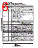
6 / 27 page  ThunderLAN ™ TNETE100PM PCI ETHERNET ™ CONTROLLER WITH POWER MANAGEMENT SINGLE-CHIP 10 BASE-T WITH MII FOR 100 BASE-T/100VG-AnyLAN SPWS026 – OCTOBER 1996 6 POST OFFICE BOX 1443 • HOUSTON, TEXAS 77251–1443 Pin Functions (Continued) PIN TYPE† DESCRIPTION NAME NO. TYPE† DESCRIPTION PCI INTERFACE (CONTINUED) PCLK 131 I PCI clock. PCLK is the clock reference for all PCI bus operations. All other PCI pins except PRST and PINTA are sampled on the rising edge of PCLK. All PCI bus timing parameters are defined with respect to this edge. PCLKRUN 53 I/O ‡ Clock run control. Powerdown-enable-configuration. The PCLKRUN pin must be connected to the PRST signal for the system. This reset is generated by the VDDI supply and, therefore, is used to put the TNETE100PM into D3off mode when SOPD = 1. When the PCLKRUN pin is asserted low, the TNETE100PM performs the following internal functions: • Disables PCLK during sleep state • Puts all PCI outputs in high impedance mode asynchonously • Disables PFRAME# to ensure that the TNETE100PM is signaled that it is doing a PCI I/O cycle • Resets all TNETE100PM internal state machines • Disables all interrupts • Sets PowerState = 11b (only if SOPD = 1) • Stops the transmitter and receiver (destructive) NOTE: Ten PCLK cycles are required for the TNETE100PM to terminate PCI operations and reset all state machines after PCLKRUN goes low. Clock run control. Clock-run-enable configuration. The PCLKRUN pin must be connected to the PCLKRUN signal of the system. PCLKRUN is the active-low PCI clock request / grant signal that allows the TNETE100PM to indicate when an active PCI clock is required. (This is an open drain.) PC / BE3 PC / BE2 PC / BE1 PC / BE0 2 16 28 41 I/O PCI bus command and byte enables: PC / BE3 enables byte 3 (MSbyte) of the PCI address/data bus. PC / BE2 enables byte 2 of PCI address / data bus. PC / BE1 enables byte 1 of PCI address / data bus. PC / BE0 enables byte 0 (LSbyte) of PCI address / data bus. PDEVSEL 21 I/O PCI device select. PDEVSEL indicates that the driving device has decoded one of its addresses as the target of the current access. The TNETE100PM drives PDEVSEL when it decodes an access to one of its registers. As a bus master, the TNETE100PM monitors PDEVSEL to detect accesses to illegal memory addresses. PFRAME 17 I/O PCI cycle frame. PFRAME is driven by the active bus master to indicate the beginning and duration of an access. PFRAME is asserted to indicate the start of a bus transaction and remains asserted during the transaction, only being deasserted in the final data phase. PGNT 132 I PCI bus grant. PGNT is asserted by the system arbiter to indicate that the TNETE100PM has been granted control of the PCI bus. PIDSEL 4 I PCI initialization device select. PIDSEL is the chip select for access to PCI configuration registers. PINTA 128 O/D PCI interrupt. PINTA is the interrupt request from the TNETE100PM. PCI interrupts are shared, so this is an open-drain (wired-OR) output. PIRDY 19 I/O PCI initiator ready. PIRDY is driven by the active bus master to indicate that it is ready to complete the current data phase of a transaction. A data phase is not completed until both PIRDY and PTRDY are sampled asserted. When the TNETE100PM is a bus master, it uses PIRDY to align incoming data on reads or outgoing data on writes with its internal RAM-access synchronization (maximum one cycle at the beginning of burst). When the TNETE100PM is a bus slave, it extends the access appropriately until both PIRDY and PTRDY are asserted. PTRDY 20 I/O PCI target ready. PTRDY is driven by the selected device (bus slave or target) to indicate that it is ready to complete the current data phase of a transaction. A data phase is not completed until both PIRDY and PTRDY are sampled asserted. ThunderLAN uses PTRDY to ensure every direct I/O (DIO) operation is correctly interlocked. PPAR 27 I/O PCI parity. PPAR carries even parity across PAD[31:0] and PC / BE[3:0]. It is driven by the TNETE100PM during all address and write cycles as a bus master and during all read cycles as a bus slave. † I = input, I / O = 3-state input / output, O / D = open-drain output ‡ Open drain |
|
|
链接网址 |
| ALLDATASHEET是否为您带来帮助? [ DONATE ] |
关于 Alldatasheet | 广告服务 | 联系我们 | 隐私政策 | 数据表链接 | 链接交换 | 制造商名单 All Rights Reserved©Alldatasheet.com |
| Russian : Alldatasheetru.com | Korean : Alldatasheet.co.kr | Spanish : Alldatasheet.es | French : Alldatasheet.fr | Italian : Alldatasheetit.com Portuguese : Alldatasheetpt.com | Polish : Alldatasheet.pl | Vietnamese : Alldatasheet.vn Indian : Alldatasheet.in | Mexican : Alldatasheet.com.mx | British : Alldatasheet.co.uk | New Zealand : Alldatasheet.co.nz |
|
Family Site : ic2ic.com |
icmetro.com |
 Chinese ▼
 English
 Chinese
 German
 Japanese
 Russian
 Korean
 Spanish
 French
 Italian
 Portuguese
 Polish
 Vietnamese
 Indian
 Mexican
 British
 New Zealand