|
数据搜索系统,热门电子元器件搜索 |
|
|
数据搜索系统,热门电子元器件搜索 |
|
PCA9536D 数据表(PDF) 4 Page - NXP Semiconductors |
|
|
|||||||||||||||||||||||||||||
PCA9536D 数据表(HTML) 4 Page - NXP Semiconductors |
|
|
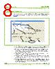
4 / 12 page  UM10206 © Koninklijke Philips Electronics N.V. 2006. All rights reserved. User manual Rev. 01 — 13 June 2006 4 of 12 Philips Semiconductors UM10206 I2C Demonstration Board 2005-1 Quick Start Guide 3. Installation 3.1 Win-I2CUSB Lite Software 1. Download the Win-I2CUSB Lite installation driver from: www.semiconductors.philips.com/products/interface_control/i2c. 2. The installation software will automatically start from the executable file. If the installation software does not start automatically double-click on the Setup.exe file. 3. For software or hardware application support email us at: i2c.support@philips.com. Do not contact The Boardshop for application support issues. 3.2 Demonstration Board hardware connection to computer USB port 1. Touch the bare metal on the rear of your computer to neutralize any ESD (static charge) before removing the Demonstration Board Hardware from the packaging. 2. Connect the hardware to a USB port using a standard USB cable. 3. The green USB_LINK LED on the hardware will illuminate. 3.3 Connecting the remote sensor diode 1. Connect the red wire to the D + pin and the white wire to the D− pin (see Figure 1). 2. Plug the remote sensor diode into the Demonstration Board (see Figure 2). (1) The cable is approximately 15cm long with the red wire connected to the emitter. (2) The 2-pin male connector is compatible with the 2-pin header on the pcb. (3) The base and collector of the transistor are connected together. Fig 1. I2C Demonstration Board 2005-1 remote sensor diode 013aaa000 D+ D − (1) (3) (2) 2N3906 |
|
|
链接网址 |
| ALLDATASHEET是否为您带来帮助? [ DONATE ] |
关于 Alldatasheet | 广告服务 | 联系我们 | 隐私政策 | 数据表链接 | 链接交换 | 制造商名单 All Rights Reserved©Alldatasheet.com |
| Russian : Alldatasheetru.com | Korean : Alldatasheet.co.kr | Spanish : Alldatasheet.es | French : Alldatasheet.fr | Italian : Alldatasheetit.com Portuguese : Alldatasheetpt.com | Polish : Alldatasheet.pl | Vietnamese : Alldatasheet.vn Indian : Alldatasheet.in | Mexican : Alldatasheet.com.mx | British : Alldatasheet.co.uk | New Zealand : Alldatasheet.co.nz |
|
Family Site : ic2ic.com |
icmetro.com |
 Chinese ▼
 English
 Chinese
 German
 Japanese
 Russian
 Korean
 Spanish
 French
 Italian
 Portuguese
 Polish
 Vietnamese
 Indian
 Mexican
 British
 New Zealand