|
数据搜索系统,热门电子元器件搜索 |
|
|
数据搜索系统,热门电子元器件搜索 |
|
AD6600ST/PCB 数据表(PDF) 16 Page - Analog Devices |
|
|
|||||||||||||||||||||||||||||
AD6600ST/PCB 数据表(HTML) 16 Page - Analog Devices |
|
|
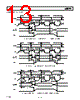
16 / 24 page  REV. 0 AD6600 –16– Table I. Attenuator and Gain Settings Attenuator Gain Amp Total RSSI Word 0 dB +18 dB +18 dB 000 0 dB +12 dB +12 dB 001 –12 dB +18 dB +6 dB 010 –12 dB +12 dB 0 dB 011 –24 dB +18 dB –6 dB 100 –24 dB +12 dB –12 dB 101 High-Speed Peak Detector and RSSI Circuitry The peak detector along with the attenuator and dual gain amplifier form the control loop within the AD6600. The peak detector is designed to follow the analog input one clock cycle before the conversion is actually made. Therefore, while the converter section of the AD6600 is converting sample “n,” the peak detector is already looking at sample “n+1.” While look- ing at the “n+1” sample (the calibration period), the peak detec- tor examines the envelope of the input signal. The more of an envelope that is tracked, the more accurate the gain setting. At the very least, the peak detector must be presented either a positive or negative sinusoidal peak, which represents about one-half of a sine wave cycle. Since the peak detector works for a complete cycle prior to conversion, the absolute minimum IF frequency that can be determined is twice the sample rate per channel. Therefore, at 15 MSPS, the minimum IF frequency that can be sampled would be 30 MHz. Note that the more cycles of the input that are monitored by the peak detector, the more accurate the gain setting will be. There- fore, the actual minimum IF frequency recommended is higher than this. The minimum specified frequency is 70 MHz. Since the RSSI control loop is performed on a sample-by-sample basis, the AD6600 very accurately follows the signals into and out of a deep fade. Hysteresis The AD6600 employs hysteresis to prevent the gain-ranging from unnecessarily changing when the signal envelope is near an RSSI threshold. The hysteresis is digital and will account for exactly 6 dB of shift, depending on whether the signal is increasing or decreasing. This effect is shown in the dashed lines of the over- all transfer function, Figure 16. External LC Noise Filter, Resonant Port The output of the attenuator/gain stage drives the wide bandwidth track-and-hold (T/H), followed by the ADC encoder. Because the attenuator/gain stage has a very wide bandwidth (~1 GHz), an LC filter or “resonant port” is provided to limit the amount of wideband noise delivered to the ADC. The simple LC filter does not provide signal selectivity and should typically be 35 MHz to 50 MHz wide. However, because the ADC’s track-and-hold itself has a wide bandwidth (~450 MHz), this noise-limiting filter is critical to meeting overall sensitivity. Specific details on select- ing components for the resonant port are provided later in the text (Understanding the External Analog Filter). ADC Encoder After the calibration period is complete (one clock cycle), the appropriate gain and attenuator settings are determined and set. Once settled, the internal track-and-hold freezes the input signal so that the ADC encoder may digitize the signal. During digiti- zation, the peak detector/RSSI circuitry is already looking at the next sample. When the AD6600 is in dual channel mode, the process is interleaved: while Channel B is monitored for signal strength, Channel A is digitized. This allows the RSSI to update on a clock-by-clock basis. DIGITIZE OLD DATA T-AND-H HOLD T-AND-H TRACK ADC DIGITIZE T-AND-H HOLD RSSI CAL. RSSI SET NOISE FILTER DISCHARGE NOISE FILTER SETTLING 4/8 AMP CLAMPED NOISE FILTER SETTLING ENCODE IF INPUT INTERNAL 2 CLOCK RSSI CALIBRATION AMPLIFIER CONTROL T/H INPUT Figure 17. Internal Timing Figure 17 shows the internal timing of the chip. The encode applied to the device initiates several actions. The first and most important is that the track-and-hold is placed in hold, thus sampling the analog input at that instant. The second action is that the peak detector of the RSSI circuitry is initialized. During this period, the analog input envelope is monitored to determine signal power. The AD6600 is in calibration mode for about one- quarter of the encode period. While the AD6600 is in calibration, the external noise filter is discharged and the amplifier driving the filter disabled. Since this filter is shared between the two input channels in dual channel mode, this greatly reduces the feedthrough between the channels that would otherwise exist. One-quarter of an encode period after the calibration is complete, the amplifier is re-enabled and allowed to settle to its new signal conditions for sampling by the wideband T/H on the next encode signal. The final action is that the signal on the resonant port is sampled by the track-and-hold. This happens on the next rising edge of the encode. Input Mode Select The AD6600 has two operating modes: single channel and dual channel. In single channel mode, the ADC always samples Chan- nel A or always samples Channel B. In dual channel mode, the ADC converter is sampling Channel A and Channel B on alter- nating Encode cycles. Two control pins are provided to select the desired mode of operation. A_SEL and B_SEL arbitrate the selection of how these input channels are connected to the out- put. Table II shows the truth table for selection of the input. |
|
|
链接网址 |
| ALLDATASHEET是否为您带来帮助? [ DONATE ] |
关于 Alldatasheet | 广告服务 | 联系我们 | 隐私政策 | 数据表链接 | 链接交换 | 制造商名单 All Rights Reserved©Alldatasheet.com |
| Russian : Alldatasheetru.com | Korean : Alldatasheet.co.kr | Spanish : Alldatasheet.es | French : Alldatasheet.fr | Italian : Alldatasheetit.com Portuguese : Alldatasheetpt.com | Polish : Alldatasheet.pl | Vietnamese : Alldatasheet.vn Indian : Alldatasheet.in | Mexican : Alldatasheet.com.mx | British : Alldatasheet.co.uk | New Zealand : Alldatasheet.co.nz |
|
Family Site : ic2ic.com |
icmetro.com |
 Chinese ▼
 English
 Chinese
 German
 Japanese
 Russian
 Korean
 Spanish
 French
 Italian
 Portuguese
 Polish
 Vietnamese
 Indian
 Mexican
 British
 New Zealand