|
数据搜索系统,热门电子元器件搜索 |
|
|
数据搜索系统,热门电子元器件搜索 |
|
LUCL9500AGF-D 数据表(PDF) 24 Page - Agere Systems |
|
|
|||||||||||||||||||||||||||||
LUCL9500AGF-D 数据表(HTML) 24 Page - Agere Systems |
|
|
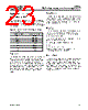
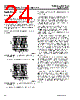
24 / 32 page  Preliminary Data Sheet September 2001 High-Voltage Ringing SLIC for VoIP Applications L9500A 24 Agere Systems Inc. Applications (continued) Power Ring The device offers a ring mode, in which a balanced power ring signal is provided to the tip/ring pair. During the ring mode, a user-supplied low-voltage ring signal is input to the device’s RINGIN input. This signal is amplified to produce the balanced power ring signal. The user may supply a sine wave input, PWM input, or a square wave to produce sinusoidal or trapezoidal ringing at tip and ring. Various crest factors are shown below for illustrative purposes. 12-3346a (F) Note: Slew rate = 5.65 V/ms; trise = tfall = 23 ms; pwidth = 2 ms; period = 50 ms. Figure 9. Ringing Waveform Crest Factor = 1.6 12-3347a (F) Note: Slew rate = 10.83 V/ms; trise = tfall = 12 ms; pwidth = 13 ms; period = 50 ms. Figure 10. Ringing Waveform Crest Factor = 1.2 Sine Wave Input Signal and Sine Wave Power Ring Signal Output The low-voltage sine wave input is applied differentially or single ended to the L9500 at pins RINGINP and RINGINN. During the ring mode, the signals at pins RINGINP and RINGINN are amplified and presented to the subscriber loop. The differential gain from RINGIN to tip and ring is a nominal 70. When the device enters the ring mode, the tip/ring overhead set at OVH and the scan clamp circuit are disabled, allowing the voltage magnitude of the power ring signal to be maximized. Additionally, in the ring mode, the loop current limit is increased 2.5X the value set by the VPROG voltage. The magnitude of the power ring voltage will be a func- tion of the gain of the ring amplifier, the high-voltage battery, and the input signal at RINGIN. The input range of the signal at RINGIN is 0 V to Vcc. As the input volt- age at RINGIN is increased, the magnitude of the power ring voltage at tip and ring will increase linearly, per the gain of 70, until the tip and ring drive amplifiers begin to saturate. Once the tip and ring amplifiers reach satura- tion, further increases of the input signal will cause clip- ping distortion of the power ring signal at tip and ring. The ring signal will appear balanced on tip and ring. That is, the power ring signal is applied to both tip and ring, with the signal on tip 180 ° out of phase from the signal on ring. It is recommended that the input level at RINGIN be adjusted so that the power ring signal at tip and ring is just at the edge or slightly clipping. This gives maxi- mum power transfer with minimal distortion of the sine wave. The tip side will saturate at a nominal 1 V above ground. The ring side will saturate at a nominal 3 V above battery. The input circuit for a sine wave along with waveforms to illustrate the tip and ring saturation is shown in Figure 9. The point at which clipping of the power ring signal begins at tip and ring is a function of the battery volt- age, the input capacitor at RINGIN, and the input signal at RINGIN and Vcc. During nonring modes, the sinusoi- dal ringing waveform may be left on at RINGIN. Via the state table, the ring signal will be removed from tip and ring even if the low-voltage input is still present at RINGIN. TIME (s) –80 –60 –40 –20 0 20 40 60 80 0.00 0.02 0.06 0.04 0.08 0.10 0.12 0.14 0.16 0.18 0.20 TIME (s) –80 –60 –40 –20 0 20 40 60 80 0.00 0.02 0.06 0.04 0.08 0.10 0.12 0.14 0.16 0.18 0.20 |
|
链接网址 |
| ALLDATASHEET是否为您带来帮助? [ DONATE ] |
关于 Alldatasheet | 广告服务 | 联系我们 | 隐私政策 | 数据表链接 | 链接交换 | 制造商名单 All Rights Reserved©Alldatasheet.com |
| Russian : Alldatasheetru.com | Korean : Alldatasheet.co.kr | Spanish : Alldatasheet.es | French : Alldatasheet.fr | Italian : Alldatasheetit.com Portuguese : Alldatasheetpt.com | Polish : Alldatasheet.pl | Vietnamese : Alldatasheet.vn Indian : Alldatasheet.in | Mexican : Alldatasheet.com.mx | British : Alldatasheet.co.uk | New Zealand : Alldatasheet.co.nz |
|
Family Site : ic2ic.com |
icmetro.com |
 Chinese ▼
 English
 Chinese
 German
 Japanese
 Russian
 Korean
 Spanish
 French
 Italian
 Portuguese
 Polish
 Vietnamese
 Indian
 Mexican
 British
 New Zealand