|
数据搜索系统,热门电子元器件搜索 |
|
|
数据搜索系统,热门电子元器件搜索 |
|
AD8232ACPZ-R7 数据表(PDF) 22 Page - Analog Devices |
|
|
|||||||||||||||||||||||||||||
AD8232ACPZ-R7 数据表(HTML) 22 Page - Analog Devices |
|
|
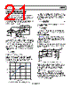
22 / 28 page  AD8232 Data Sheet Rev. A | Page 22 of 28 Additional High-Pass Filtering Options In addition to the topologies explained in the previous sections, an additional pole may be added to the dc blocking circuit for additional rejection of low frequency signals. This configuration is shown in Figure 56. Figure 56. Schematic for an Alternative Two-Pole High-Pass Filter An extra benefit of this circuit topology is that it allows lower cutoff frequency with lower R and C values and the resistor, RCOMP, can be used to control the Q of the filter to achieve narrow band-pass filters (for heart rate detection) or maximum pass- band flatness (for cardiac monitoring). With this topology, the filter attenuation reverts to a single pole roll off at very low frequencies. Because the initial roll off was 40 dB per decade, this reversion to 20 dB per decade has little impact on the ability of the filter to reject out-of-band low frequency signals. The designer may choose different values to achieve the desired filter performance. To simplify the design process, use the following recommendations as a starting point for component value selection. R1 = R2 ≥ 100 kΩ C1 = C2 RCOMP = 0.14 × R1 The cutoff frequency is located at C2 R2 C1 R1 f C 2 10 The selection of RCOMP to be 0.14 times the value of the other two resistors optimizes the filter for a maximally flat pass band. Reduce its value to increase the Q and, consequently, the peaking of the filter. Keep in mind that a very low value of RCOMP can result in an unstable circuit. The selection of values based on these criteria result in a transfer function similar to the one shown in Figure 58. When additional low frequency rejection is desired, a high-order high-pass filter can be implemented by adding an ac coupling network at the output of the instrumentation amplifier, as shown in Figure 57. The SW terminal is connected to the ac coupling network to obtain the best settling time response when fast restore engages. Figure 57. Schematic for a Three-Pole High-Pass Filter Figure 58. Frequency Response of Circuits in Figure 56 and Figure 57 Careful analysis and adjustment of all of the component values in practice is recommended to optimize the filter characteristics. A useful hint is to reduce the value of RCOMP to increase the peaking of the active filter to overcome the additional roll off introduced by the ac coupling network. Proper adjustment can yield the best pass-band flatness. The design of the high-pass filter involves tradeoffs between signal distortion, component count, low frequency rejection, and component sizes. For example, a single-pole high-pass filter results in the least distortion to the signal, but its rejection of low-frequency artifacts is the lowest Table 4 compares the recommended filtering options. Table 4. Comparison of High-Pass Filtering Options Filter Order Component Count Low Frequency Rejection Capacitor Sizes/Values Signal Distortion1 Output Impedance2 Figure 53 1 2 Good Large Low Low Figure 55 2 4 Better Large Medium Higher Figure 56 2 5 Better Smaller Medium Low Figure 57 3 7 Best Smaller Highest Higher 1 For equivalent corner frequency location. 2 Output impedance refers to the drive capability of the high-pass filter before the low-pass filter. Low output impedance is desirable to allow flexibility in the selection of values for a low-pass filter, as explained in the Low-Pass Filtering and Gain section. 10kΩ IAOUT HPSENSE HPDRIVE S1 +IN –IN HPA SW 10kΩ S2 6 REFOUT 8 TO NEXT STAGE = REFOUT 19 3 1 20 2 C1 R1 R2 RCOMP C2 10kΩ IAOUT HPSENSE HPDRIVE S1 +IN –IN HPA SW 10kΩ S2 6 REFOUT 8 TO NEXT STAGE = REFOUT 19 3 1 20 2 C1 C3 R1 R2 RCOMP C2 R3 60 40 20 0 –20 –40 –60 0.01 100 10 1 0.1 FREQUENCY (Hz) THREE-POLE FILTER TWO-POLE FILTER 40dB PER DECADE 40dB PER DECADE 20dB PER DECADE 60dB PER DECADE |
|
|
链接网址 |
| ALLDATASHEET是否为您带来帮助? [ DONATE ] |
关于 Alldatasheet | 广告服务 | 联系我们 | 隐私政策 | 数据表链接 | 链接交换 | 制造商名单 All Rights Reserved©Alldatasheet.com |
| Russian : Alldatasheetru.com | Korean : Alldatasheet.co.kr | Spanish : Alldatasheet.es | French : Alldatasheet.fr | Italian : Alldatasheetit.com Portuguese : Alldatasheetpt.com | Polish : Alldatasheet.pl | Vietnamese : Alldatasheet.vn Indian : Alldatasheet.in | Mexican : Alldatasheet.com.mx | British : Alldatasheet.co.uk | New Zealand : Alldatasheet.co.nz |
|
Family Site : ic2ic.com |
icmetro.com |
 Chinese ▼
 English
 Chinese
 German
 Japanese
 Russian
 Korean
 Spanish
 French
 Italian
 Portuguese
 Polish
 Vietnamese
 Indian
 Mexican
 British
 New Zealand