|
数据搜索系统,热门电子元器件搜索 |
|
|
数据搜索系统,热门电子元器件搜索 |
|
AD8232ACPZ-R7 数据表(PDF) 23 Page - Analog Devices |
|
|
|||||||||||||||||||||||||||||
AD8232ACPZ-R7 数据表(HTML) 23 Page - Analog Devices |
|
|
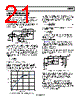
23 / 28 page  Data Sheet AD8232 Rev. A | Page 23 of 28 LOW-PASS FILTERING AND GAIN The AD8232 includes an uncommitted op amp that can be used for extra gain and filtering. For applications that do not require a high-order filter, a simple RC low-pass filter should suffice, and the op amp can buffer or further amplify the signal. Figure 59. Schematic for a Single-Pole Low-Pass Filter and Additional Gain Applications that require a steeper roll off or a sharper cut off, a Sallen-Key filter topology can be implemented, as shown in Figure 60. Figure 60. Schematic for a Two-Pole Low-Pass Filter The following equations describe the low-pass cut off frequency, gain, and Q: fC = 1/(2π√(R1 C1 R2 C2)) Gain = 1 + R3/R4 Gain C1 R1 C R2 C2 R1 C2 R2 C1 R1 Q 1 2 Note that changing the gain has an effect on Q and vice versa. Common values for Q are 0.5 to avoid peaking or 0.7 for maximum flatness and sharp cut off. A high value of Q can be used in narrow-band applications to increase peaking and the selectivity of the band-pass filter. A common design procedure is to set R1 = R2 = R and C1 = C2 = C, which simplifies the expressions for cutoff frequency and Q to fC = 1/(2πRC) Gain Q 3 1 Note that Q can be controlled by setting the gain with R3 and R4; however, this limits the gain to be less than 3. For gain values equal to or greater than 3, the circuit becomes unstable. A simple modification that allows higher gains is to make the value of C2 at least four times larger than C1. It is important to note that these design equations only hold true in the case that the output impedance of the previous stage is much lower than the input impedance of the Sallen-Key filter. This is not the case when using an ac coupling network between the instrumentation amplifier output and the input of the low- pass filter without a buffer. To connect these two filtering stages properly without a buffer, make the value of R1 at least ten times larger than the resistor of the ac coupling network (labeled as R2 in Figure 55). DRIVING ANALOG-TO-DIGITAL CONVERTERS The ability of AD8232 to drive capacitive loads makes it ideal to drive an ADC without the need for an additional buffer. However, depending on the input architecture of the ADC, a simple low- pass RC network may be required to decouple the transients from the switched-capacitor input typical of modern ADCs. This RC network also acts as an additional filter that can help reduce noise and aliasing. Follow the recommended guidelines from the ADC data sheet for the selection of proper R and C values. Figure 61. Driving an ADC DRIVEN ELECTRODE A driven lead (or reference electrode) is often used to minimize the effects of common-mode voltages induced by the power line and other interfering sources. The AD8232 extracts the common- mode voltage from the instrumentation amplifier inputs and makes it available through the RLD amplifier to drive an opposing signal into the patient. This functionality maintains the voltage between the patient and the AD8232 at a near constant, greatly improving the common-mode rejection ratio. As a safety measure, place a resistor between the RLD pin and the electrode connected to the subject to ensure that current flow never exceeds 10 μA. Calculate the value of this resistor to be equal to the supply voltage across the AD8232 divided by 10 μA. The AD8232 implements an integrator formed by an internal 150 kΩ resistor and an external capacitor to drive this electrode. Choice of the integrator capacitor is a tradeoff between line rejec- tion capability and stability. The capacitor should be small to maintain as much loop gain as possible, around 50 Hz and 60 Hz, which are typical line frequencies. For stability, the gain of the integrator should be less than unity at the frequency of any other poles in the loop, such as those formed by the patient’s capacitance and the safety resistors. The suggested application circuits use a 1 nF capacitor, which results in a loop gain of about 20 at line frequencies, with a crossover frequency of about 1 kHz. In a two-lead configuration, the RLD amplifier can be used to drive the bias current resistors on the inputs. Although not as effective as a true driven electrode, this configuration can provide some common-mode rejection improvement if the sense electrode impedance is small and well matched. REFOUT FILTERED SIGNAL A1 FROM IN-AMP STAGE C R REFOUT FILTERED SIGNAL A1 FROM IN-AMP STAGE C2 C1 R2 R3 R4 R1 A1 C R ADC 10 AD8232 |
|
|
链接网址 |
| ALLDATASHEET是否为您带来帮助? [ DONATE ] |
关于 Alldatasheet | 广告服务 | 联系我们 | 隐私政策 | 数据表链接 | 链接交换 | 制造商名单 All Rights Reserved©Alldatasheet.com |
| Russian : Alldatasheetru.com | Korean : Alldatasheet.co.kr | Spanish : Alldatasheet.es | French : Alldatasheet.fr | Italian : Alldatasheetit.com Portuguese : Alldatasheetpt.com | Polish : Alldatasheet.pl | Vietnamese : Alldatasheet.vn Indian : Alldatasheet.in | Mexican : Alldatasheet.com.mx | British : Alldatasheet.co.uk | New Zealand : Alldatasheet.co.nz |
|
Family Site : ic2ic.com |
icmetro.com |
 Chinese ▼
 English
 Chinese
 German
 Japanese
 Russian
 Korean
 Spanish
 French
 Italian
 Portuguese
 Polish
 Vietnamese
 Indian
 Mexican
 British
 New Zealand