|
数据搜索系统,热门电子元器件搜索 |
|
|
数据搜索系统,热门电子元器件搜索 |
|
AD8210YR-R7 数据表(PDF) 14 Page - Analog Devices |
|
|
|||||||||||||||||||||||||||||
AD8210YR-R7 数据表(HTML) 14 Page - Analog Devices |
|
|
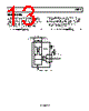
14 / 16 page  AD8210 Data Sheet Rev. D | Page 14 of 16 APPLICATIONS INFORMATION The AD8210 is ideal for high-side or low-side current sensing. Its accuracy and performance benefits applications, such as 3-phase and H-bridge motor control, solenoid control, and power supply current monitoring. For solenoid control, two typical circuit configurations are used: high-side current sense with a low-side switch, and high-side current sense with a high-side switch. HIGH-SIDE CURRENT SENSE WITH A LOW-SIDE SWITCH In this case, the PWM control switch is ground referenced. An inductive load (solenoid) is tied to a power supply. A resistive shunt is placed between the switch and the load (see Figure 33). An advantage of placing the shunt on the high side is that the entire current, including the recirculation current, can be meas- ured because the shunt remains in the loop when the switch is off. In addition, diagnostics can be enhanced because short circuits to ground can be detected with the shunt on the high side. INDUCTIVE LOAD CLAMP DIODE BATTERY SHUNT SWITCH NC = NO CONNECT 5V +IN VREF1 +VS OUT –IN GND VREF2 NC AD8210 0.1µF Figure 33. Low-Side Switch In this circuit configuration, when the switch is closed, the common-mode voltage moves down to the negative rail. When the switch is opened, the voltage reversal across the inductive load causes the common-mode voltage to be held one diode drop above the battery by the clamp diode. HIGH-SIDE CURRENT SENSE WITH A HIGH-SIDE SWITCH This configuration minimizes the possibility of unexpected solenoid activation and excessive corrosion (see Figure 34). In this case, both the switch and the shunt are on the high side. When the switch is off, the battery is removed from the load, which prevents damage from potential short circuits to ground, while still allowing the recirculation current to be measured and diagnostics to be preformed. Removing the power supply from the load for the majority of the time minimizes the corrosive effects that could be caused by the differential voltage between the load and ground. INDUCTIVE LOAD CLAMP DIODE BATTERY SHUNT SWITCH NC = NO CONNECT 5V +IN VREF1 +VS OUT –IN GND VREF2 NC AD8210 0.1µF Figure 34. High-Side Switch Using a high-side switch connects the battery voltage to the load when the switch is closed. This causes the common-mode voltage to increase to the battery voltage. In this case, when the switch is opened, the voltage reversal across the inductive load causes the common-mode voltage to be held one diode drop below ground by the clamp diode. H-BRIDGE MOTOR CONTROL Another typical application for the AD8210 is as part of the control loop in H-bridge motor control. In this case, the AD8210 is placed in the middle of the H-bridge (see Figure 35) so that it can accurately measure current in both directions by using the shunt available at the motor. This configuration is beneficial for measuring the recirculation current to further enhance the control loop diagnostics. SHUNT 2.5V 5V CONTROLLER NC = NO CONNECT MOTOR 5V +IN VREF1 +VS OUT –IN GND VREF2 NC AD8210 0.1µF Figure 35. Motor Control Application The AD8210 measures current in both directions as the H-bridge switches and the motor changes direction. The output of the AD8210 is configured in an external reference bidirectional mode (see the Modes of Operation section). |
|
|
链接网址 |
| ALLDATASHEET是否为您带来帮助? [ DONATE ] |
关于 Alldatasheet | 广告服务 | 联系我们 | 隐私政策 | 数据表链接 | 链接交换 | 制造商名单 All Rights Reserved©Alldatasheet.com |
| Russian : Alldatasheetru.com | Korean : Alldatasheet.co.kr | Spanish : Alldatasheet.es | French : Alldatasheet.fr | Italian : Alldatasheetit.com Portuguese : Alldatasheetpt.com | Polish : Alldatasheet.pl | Vietnamese : Alldatasheet.vn Indian : Alldatasheet.in | Mexican : Alldatasheet.com.mx | British : Alldatasheet.co.uk | New Zealand : Alldatasheet.co.nz |
|
Family Site : ic2ic.com |
icmetro.com |
 Chinese ▼
 English
 Chinese
 German
 Japanese
 Russian
 Korean
 Spanish
 French
 Italian
 Portuguese
 Polish
 Vietnamese
 Indian
 Mexican
 British
 New Zealand