|
数据搜索系统,热门电子元器件搜索 |
|
|
数据搜索系统,热门电子元器件搜索 |
|
AD8051ARTZ-R2 数据表(PDF) 21 Page - Analog Devices |
|
|
|||||||||||||||||||||||||||||
AD8051ARTZ-R2 数据表(HTML) 21 Page - Analog Devices |
|
|
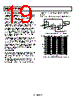
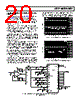
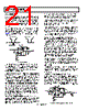
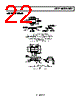
21 / 25 page  AD8051/AD8052/AD8054 Rev. J | Page 20 of 24 SYNC STRIPPER Synchronizing pulses are sometimes carried on video signals so as not to require a separate channel to carry the synchronizing information. However, for some functions, such as analog-to- digital conversion, it is not desirable to have the sync pulses on the video signal. These pulses reduce the dynamic range of the video signal and do not provide any useful information for such a function. A sync stripper removes the synchronizing pulses from a video signal while passing all the useful video information. Figure 51 shows a practical single-supply circuit that uses only a single AD8051. It is capable of directly driving a reverse terminated video line. AD8051 0.1µF 10µF + 100Ω TO A/D 3V OR 5V VBLANK GROUND 0.4V VIDEO WITH SYNC GROUND VIDEO WITHOUT SYNC R2 1kΩ R1 1kΩ VIN 3 2 7 4 6 0.8V (OR 2 × VBLANK) Figure 51. Sync Stripper The video signal plus sync is applied to the noninverting input with the proper termination. The amplifier gain is set to 2 via the two 1 kΩ resistors in the feedback circuit. A bias voltage must be applied to R1 so that the input signal has the sync pulses stripped at the proper level. The blanking level of the input video pulse is the desired place to remove the sync information. This level is multiplied by 2 by the amplifier. This level must be at ground at the output for the sync stripping action to take place. Since the gain of the amplifier from the input of R1 to the output is −1, a voltage equal to 2 × VBLANK must be applied to make the blanking level come out at ground. SINGLE-SUPPLY COMPOSITE VIDEO LINE DRIVER Many composite video signals have their blanking level at ground and have video information that is both positive and negative. Such signals require dual-supply amplifiers to pass them. However, by ac level shifting, a single-supply amplifier can be used to pass these signals. The following complications can arise from such techniques. Signals of bounded peak-to-peak amplitude that vary in duty cycle require larger dynamic swing capacity than their (bounded) peak-to-peak amplitude after they are ac-coupled. As a worst case, the dynamic signal swing will approach twice the peak-to- peak value. The two conditions that define the maximum dynamic swing requirements are a signal that is mostly low but goes high with a duty cycle that is a small fraction of a percent, and the other extreme defined by the opposite condition. The worst case of composite video is not quite this demanding. One bounding condition is a signal that is mostly black for an entire frame but has a white (full amplitude) minimum width spike at least once in a frame. The other extreme is for a full white video signal. The blanking intervals and sync tips of such a signal have negative-going excursions in compliance with the composite video specifications. The combination of horizontal and vertical blanking intervals limit such a signal to being at the highest (white) level for a maximum of about 75% of the time. As a result of the duty cycles between the two extremes previously presented, a 1 V p-p composite video signal that is multiplied by a gain of 2 requires about 3.2 V p-p of dynamic voltage swing at the output for an op amp to pass a composite video signal of arbitrarily varying duty cycle without distortion. Some circuits use a sync tip clamp to hold the sync tips at a relatively constant level to lower the amount of dynamic signal swing required. However, these circuits can have artifacts, such as sync tip compression, unless they are driven by a source with a very low output impedance. The AD8051/AD8052/AD8054 have adequate signal swing when running on a single 5 V supply to handle an ac-coupled composite video signal. The input to the circuit in Figure 52 is a standard composite (1 V p-p) video signal that has the blanking level at ground. The input network level shifts the video signal by means of ac coupling. The noninverting input of the op amp is biased to half of the supply voltage. The feedback circuit provides unity gain for the dc-biasing of the input and provides a gain of 2 for any signals that are in the video bandwidth. The output is ac-coupled and terminated to drive the line. The capacitor values were selected for providing minimum tilt or field time distortion of the video signal. These values would be required for video that is considered to be studio or broadcast quality. However, if a lower consumer grade of video, sometimes referred to as consumer video, is all that is desired, the values and the cost of the capacitors can be reduced by as much as a factor of five with minimum visible degradation in the picture. AD8051 5V + 10µF 4.99kΩ 220µF + 1000µF 0.1µF 10kΩ + 47µF 4.99kΩ 0.1µF 10µF + COMPOSITE VIDEO IN 3 2 7 4 6 RG 1kΩ RF 1kΩ RT 75Ω RL 75Ω VOUT RBT 75Ω Figure 52. Single-Supply Composite Video Line Driver |
|
|
链接网址 |
| ALLDATASHEET是否为您带来帮助? [ DONATE ] |
关于 Alldatasheet | 广告服务 | 联系我们 | 隐私政策 | 数据表链接 | 链接交换 | 制造商名单 All Rights Reserved©Alldatasheet.com |
| Russian : Alldatasheetru.com | Korean : Alldatasheet.co.kr | Spanish : Alldatasheet.es | French : Alldatasheet.fr | Italian : Alldatasheetit.com Portuguese : Alldatasheetpt.com | Polish : Alldatasheet.pl | Vietnamese : Alldatasheet.vn Indian : Alldatasheet.in | Mexican : Alldatasheet.com.mx | British : Alldatasheet.co.uk | New Zealand : Alldatasheet.co.nz |
|
Family Site : ic2ic.com |
icmetro.com |
 Chinese ▼
 English
 Chinese
 German
 Japanese
 Russian
 Korean
 Spanish
 French
 Italian
 Portuguese
 Polish
 Vietnamese
 Indian
 Mexican
 British
 New Zealand