|
数据搜索系统,热门电子元器件搜索 |
|
|
数据搜索系统,热门电子元器件搜索 |
|
L6393DTR 数据表(PDF) 5 Page - STMicroelectronics |
|
|
|||||||||||||||||||||||||||||
L6393DTR 数据表(HTML) 5 Page - STMicroelectronics |
|
|
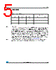
5 / 19 page  L6393 Truth table Doc ID 14497 Rev 4 5/19 3 Truth table Note: X: don’t care In the L6393 IC the two input signals PHASE and BRAKE are fed into an AND logic port and the resulting signal is in phase with the high side output HVG and in opposition of phase with the low side output LVG. This means that if BRAKE is kept to high level, the PHASE signal drives the half-bridge in phase with the HVG output and in opposition of phase with the LVG output. If BRAKE is set to low level the low side output LVG is always ON and the high side output HVG is always OFF, whatever the PHASE signal. This kind of logic interface provides the possibility to control the power stages using the PHASE signal to select the current direction in the bridge and the BRAKE signal to perform current slow decay on the low sides. From the point of view of the logic operations the two signals PHASE and BRAKE are completely equivalent, that means the two signals can be exchanged without any change in the behavior on the resulting output signals (see the Figure 1 on page 3). Note: The dead time between the turn OFF of one power switch and the turn ON of the other power switch is defined by the resistor connected between DT pin and the ground. Table 3. Truth table Inputs Outputs SD PHASE BRAKE LVG HVG L X X L L H L L H L H L H H L H H L H L H H H L H |
|
|
链接网址 |
| ALLDATASHEET是否为您带来帮助? [ DONATE ] |
关于 Alldatasheet | 广告服务 | 联系我们 | 隐私政策 | 数据表链接 | 链接交换 | 制造商名单 All Rights Reserved©Alldatasheet.com |
| Russian : Alldatasheetru.com | Korean : Alldatasheet.co.kr | Spanish : Alldatasheet.es | French : Alldatasheet.fr | Italian : Alldatasheetit.com Portuguese : Alldatasheetpt.com | Polish : Alldatasheet.pl | Vietnamese : Alldatasheet.vn Indian : Alldatasheet.in | Mexican : Alldatasheet.com.mx | British : Alldatasheet.co.uk | New Zealand : Alldatasheet.co.nz |
|
Family Site : ic2ic.com |
icmetro.com |
 Chinese ▼
 English
 Chinese
 German
 Japanese
 Russian
 Korean
 Spanish
 French
 Italian
 Portuguese
 Polish
 Vietnamese
 Indian
 Mexican
 British
 New Zealand